Acceleration and deceleration look-ahead control method for high-speed machining of numerical control machine tool

A technology of CNC machine tools and control methods, which is applied in the directions of computer control, program control, general control system, etc., and can solve the problems of complicated calculation of S-shaped curve acceleration and deceleration planning and so on.

Inactive Publication Date: 2012-04-18
SHANGHAI UNIV
View PDF3 Cites 36 Cited by
  • Summary
  • Abstract
  • Description
  • Claims
  • Application Information

AI Technical Summary

Problems solved by technology

[0004] Aiming at the problems in the prior art that there is a roundness mutation in the speed planning of the numerical control system during the acceleration and deceleration phase, which causes severe mechanical vibration when the numerical control machine tool moves, and the calculation of the acceleration and deceleration planning of the S-shaped curve is complicated, the purpose of the present invention is to provide a method that ensures Acceleration and deceleration forward-looking control method for high-speed machining of CNC machine tools, which greatly improves the processing efficiency and effectively avoids the flexible impact of the machine tool.

Method used


Image

  • Acceleration and deceleration look-ahead control method for high-speed machining of numerical control machine tool
  • Acceleration and deceleration look-ahead control method for high-speed machining of numerical control machine tool
  • Acceleration and deceleration look-ahead control method for high-speed machining of numerical control machine tool

Examples


Embodiment 1

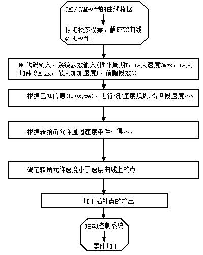
[0037] see figure 1 , the forward-looking control method of acceleration and deceleration for high-speed machining of CNC machine tools, including the following steps: the curve data of the CAD / CAM model is cut into an NC curve data model, and on the basis of the NC code, the overall calculation of the micro-segment is carried out to obtain its S S-shaped speed curve and the corresponding speed of each segment on the S-shaped speed curve (i=1:N, N is the number of forward-looking segments); determine the allowable passing speed of the transfer angle in the micro-segment (i=1:N); Determine the point where the allowable speed of the corner is less than the planned speed; thus obtain an S-shaped speed curve with the highest efficiency, and finally output the processing interpolation point to the motion control system.

Embodiment 2

[0039] see figure 1 , figure 2 , image 3 , Figure 4 and Figure 5 , the present embodiment is the same as Embodiment 1, and the special innovations are as follows:

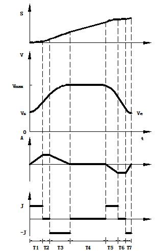
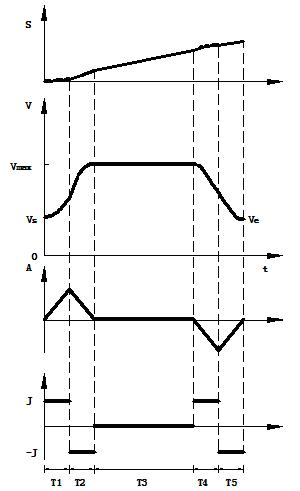
[0040] The overall S-shaped speed planning of the micro-segment and the corresponding speed of each segment on the S-shaped speed curve (i=1:N, N is the number of forward-looking segments) is determined based on the NC code generated by the numerical control system, according to the value of the data point on the model and the calculation formula for the segment length between two adjacent coordinate points to calculate the segment length L value, to get the segment length L between two adjacent coordinate points, and according to the overall segment length, initial velocity vs, and final velocity ve model, the overall calculation can be carried out in the forward-looking segment, and its S-shaped velocity curve can be obtained, and the phase of each segment can be obtained. The corresponding speed value ...

Embodiment 3

[0051] The acceleration and deceleration forward-looking control method for high-speed machining of CNC machine tools is based on the S-shaped acceleration and deceleration speed law curve model, and the corresponding speed of each segment on the S-shaped speed curve is considered comprehensively. (i=1:N, N is the number of forward-looking segments), the allowable passing speed of the micro-segment transfer angle (i=1:N), determine the reasonable speed that micro-segment machining can pass, and thus obtain an S-shaped speed curve with the highest efficiency. The present invention scheme such as figure 1 Shown:

[0052] According to the input workpiece processing data, on the basis of the NC code generated by the CNC system, firstly calculate the overall calculation in the forward-looking segment according to the known conditions (micro-segment segment length L, initial velocity vs, final velocity ve), and obtain its S-shaped velocity Curve, and at the same time, the corre...


PUM


Abstract

The invention relates to an acceleration and deceleration look-ahead control method for the high-speed machining of a numerical control machine tool. The method comprises the following operation steps of: (1) cutting the curve data of a CAD/CAM (Computer-Aided Design/Computer-Aided Manufacturing) model into a NC (Numerical Control) curve data model according to a contour error; (2) inputting system parameters, such as interpolation cycle T, maximum speed Vmax, and the like, on the basis of a NC code; (3) carrying out microfield integral S-shaped speed planning on the basis of the system parameters and determining the corresponding speed (i is equal to 1:N, N is a look-ahead field number, that is to say, a speed value from the first field to the Nth field is determined) of all fields on a S-shaped speed curve; (4) determining a microfield adapting angle allowed passing speed (i is equal to 1:N); (5) determining a point at which the adapting angle allowed speed is smaller than planned speed; (6) outputting a machining interpolation point; and (7) executing the information and finishing the machining of parts by a motion control system. In the step (5), the reasonable speed at which the microfield machining can be carried out is determined on the basis of comparing the speed on the S-shaped speed curve with the adapting angle allowed passing speed, and thereby, the S-shaped speedcurve with highest efficiency is obtained; and finally, the machining interpolation point is output to the motion control system. According to the method, the machining precision is ensured, the machining efficiency is greatly increased, the flexible impact of the machine tool is effectively prevented and the service life of the machine tool and cutters is prolonged.

Description

technical field [0001] The invention relates to an acceleration and deceleration control method for high-speed machining of a numerical control machine tool, belonging to the technical field of numerical control. Specifically, it is a method to calculate an S-shaped speed curve with the highest efficiency under the premise of ensuring the processing accuracy and the speed allowed to pass through the micro-segment junction. Background technique [0002] High-speed and high-precision is the current development trend of CNC systems, and acceleration and deceleration control is one of the core technologies of high-speed CNC systems. [0003] The traditional speed planning method takes each small path as the research object, and guarantees the machining accuracy by assuming that the starting and ending speeds of the path segment are zero. Although this method can ensure the joint point of the tool path, the processing accuracy and speed can meet the requirements for ordinary cur...

Claims


Application Information

Patent Timeline
Patent Type & Authority Applications(China)
IPC IPC(8): G05B19/4097
Inventor 陈胜刘玉山施群陈伟张武杰王玉进赵幸福程然
Owner SHANGHAI UNIV
Why Eureka
Try Eureka