Lighting unit

A lighting unit and lighting module technology, applied in lighting devices, lighting and heating equipment, components of lighting devices, etc., can solve problems such as expensive, cumbersome tasks, and bulky lighting systems

Inactive Publication Date: 2012-04-18
KONINKLIJKE PHILIPS NV
View PDF7 Cites 5 Cited by
  • Summary
  • Abstract
  • Description
  • Claims
  • Application Information

AI Technical Summary

Problems solved by technology

Conventional modular lighting systems using light sources such as incandescent bulbs can be disassembled and reassembled to assume another form, but this is generally a tedious task
Furthermore, these lighting systems are bulky due to the light sources and the amount of cables involved, and once assembled they generally remain permanently fixed, making their inherent modular nature not truly exploitable
Additionally, these types of lighting systems are often prohibitively expensive for the average consumer

Method used


Image

  • Lighting unit
  • Lighting unit
  • Lighting unit

Examples


Embodiment Construction

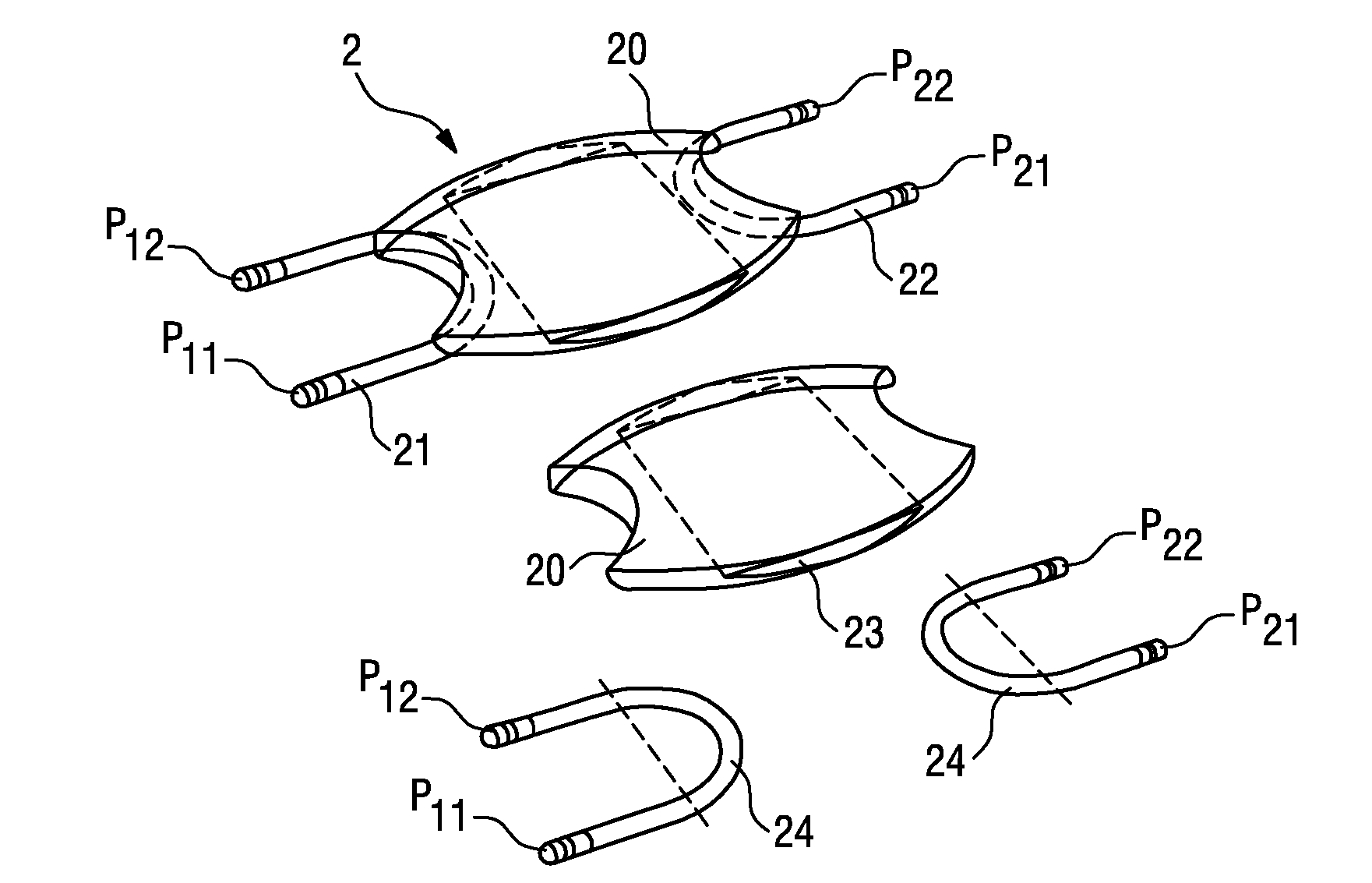
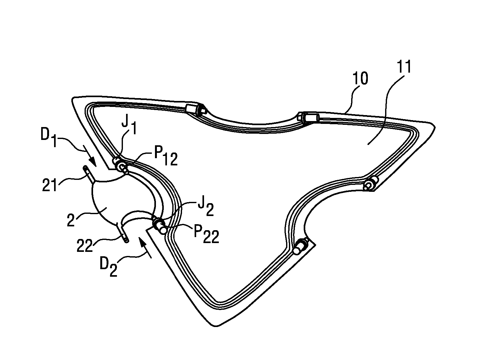
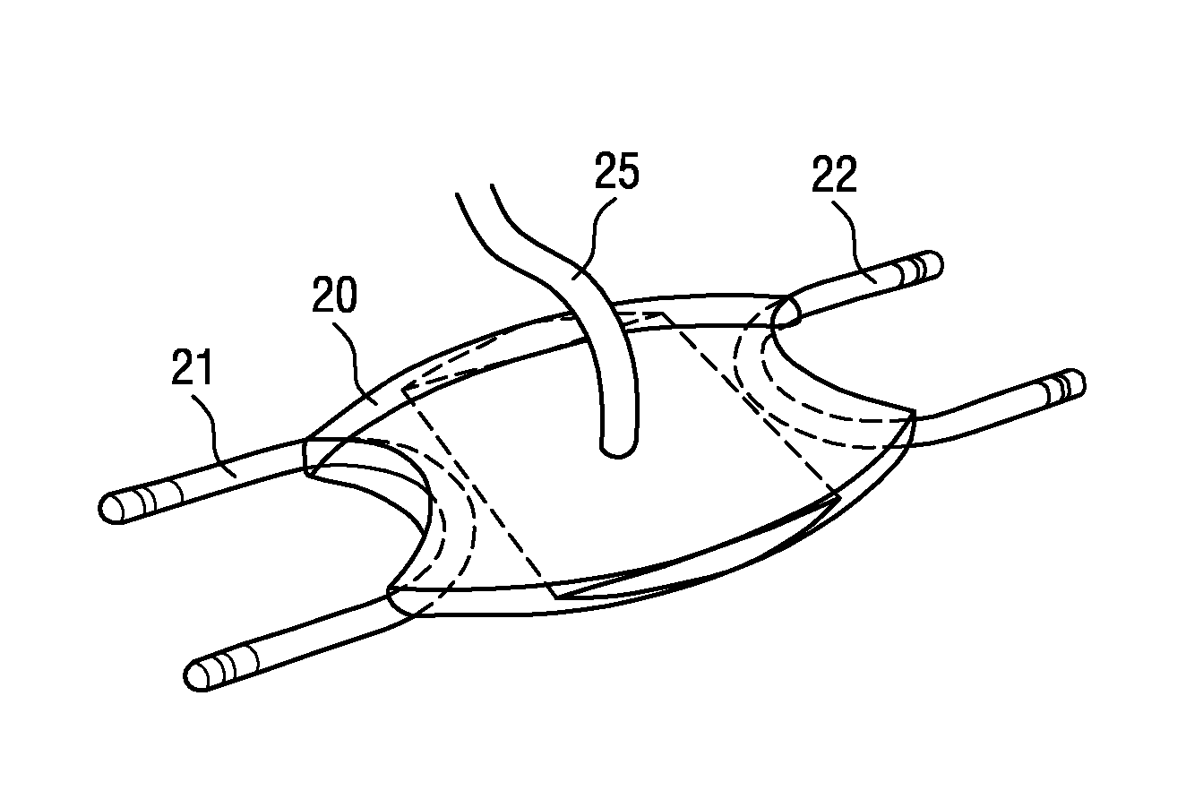
[0054] in Figure 1a Shown in for assembly Figure 5a-5c A schematic representation of a part of the lighting module 10 according to the invention of the lighting unit shown in. In order to explain the configuration of the lighting module 10, the upper part of the housing 12 is not shown. In this embodiment, the lighting module 10 is basically triangular in shape. The lighting module 10 includes a housing 12-basically a two-part frame-containing an OLED 11 that provides a light-emitting surface over the entire area of ​​the lighting module 10. Because the OLED 11 can be very thin, the overall thickness of the lighting module 10 shown here can be in the range of several millimeters. The area of ​​the light-emitting surface can be defined by selecting the type of OLED used. As known to those skilled in the art, OLEDs are driven by applying a potential between two electrodes-cathode and anode-in a conventional manner.

[0055] The figure shows a triangular lighting module 10 with ...


PUM


Abstract

The invention describes a lighting unit (1), comprising a plurality of lighting modules (10) and a number of connecting elements (2) with coupling means (21, 22), wherein each lighting element (10) comprises at least one planar light-emitting element (11) in an enclosure (12) and a number of counter-coupling means (J1, J2) arranged along at least one edge of the enclosure (12); and wherein neighbouring lighting modules (10) are coupled together detachably by means of at least one connecting element (2) such that the light-emitting element (11) of a first lighting module (10) is electrically connected to the light-emitting element (11) of a second lighting module (10) by an interaction of at least part of the coupling means (21, 22) of the connecting element (2) and at least part of the counter-coupling means (J1, J2) of the corresponding lighting modules (10). The invention also describes a connecting element (2) and a lighting module (10) for assembling such a lighting unit (1).

Description

Technical field [0001] The invention describes a lighting unit, a connecting element and a lighting module. Background technique [0002] In modern lighting solutions, many different types of lighting arrangements are possible due to different types of light sources such as incandescent bulbs, fluorescent tubes, light-emitting diodes and the different ways they can be combined into the lighting unit. Moreover, the trend towards more individuality is noteworthy, making it possible to observe the demand for more unconventional types of lighting systems, such as modular lighting arrangements that can be assembled in different ways. Conventional modular lighting systems using light sources such as incandescent bulbs can be disassembled and reassembled to take on another form, but in general this is a tedious task. In addition, due to the number of light sources and the number of cables included, these lighting systems are cumbersome. Once assembled, they generally remain permanently...

Claims


Application Information

Patent Timeline
Patent Type & Authority Applications(China)
IPC IPC(8): F21S2/00F21V23/06F21Y101/02
CPCF21Y2105/008F21S2/005F21V23/06F21Y2105/00F21Y2115/15H10K50/805H10K50/00
Inventor D.M.罗拉英
Owner KONINKLIJKE PHILIPS NV
Why Eureka
Try Eureka