
Deoiling apparatus for cooling waste gas of TRT bearing box

A technology of deoiling device and bearing box, which is applied to the separation of dispersed particles, chemical instruments and methods, separation methods, etc., can solve the problems of lubricating oil waste, environmental pollution, etc., and achieve improved deoiling effect, good cooling and adsorption effect Effect

Inactive Publication Date: 2012-04-25
SHANDONG IRON & STEEL CO LTD
View PDF5 Cites 1 Cited by
  • Summary
  • Abstract
  • Description
  • Claims
  • Application Information

AI Technical Summary

Problems solved by technology

During the entire cooling process, due to the contact between nitrogen and lubricating oil, the cooled exhaust gas carries a large amount of lubricating oil, and direct discharge not only pollutes the environment, but also causes a waste of lubricating oil

Method used


Image

  • Deoiling apparatus for cooling waste gas of TRT bearing box
  • Deoiling apparatus for cooling waste gas of TRT bearing box

Examples


Embodiment Construction

[0020] The invention is described in detail below with specific embodiments:

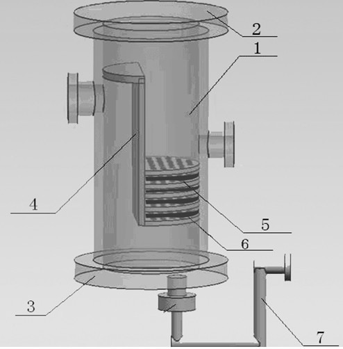
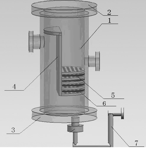
[0021] Such as figure 1 As shown, a deoiling device for cooling exhaust gas of a TRT bearing box includes a tank body 1, an air inlet and an exhaust port are arranged on the tank body 1, and an oil baffle plate is arranged on the inlet direction of the air inlet in the tank body 1 4. Along the gas flow direction, there is an oil removal plate 5 at the front of the exhaust pipe; the upper and lower ends of the tank body 1 are equipped with an upper flange 2 and a lower flange 3 for maintenance.

[0022] The bottom of the tank body is provided with an oil discharge pipe, and the oil discharge pipe adopts the structure of a U-shaped pipe 7, and the other end of the U-shaped pipe 7 communicates with the fuel tank.

[0023] The oil baffle plate 4 in the air intake direction is perpendicular to the air inlet and is at a distance from the bottom end of the tank body. The upper end and both sides of the oi...


PUM


Abstract

The present invention discloses a deoiling apparatus for cooling waste gas of a TRT bearing box. The deoiling apparatus is characterized in that: the deoiling apparatus comprises a tank; the tank is provided with a gas inlet and a gas outlet; an oil baffle is arranged inside the tank in a gas entering direction of the gas inlet; deoiling plates are arranged on the front part of a gas exhaust pipe along a gas flowing direction. Compared to the prior art, with the deoiling apparatus of the present invention, the lubricating oil carried by the waste gas is recovered so as to reduce the complement amount of the oil, avoid the waste, and effectively eliminate the pollution.

Description

technical field [0001] The invention belongs to the technical field of TRT systems in metallurgical enterprises, in particular to a deoiling device for cooling waste gas of a TRT bearing box. Background technique [0002] The bearing box on the exhaust side of the straight row TRT is located in the exhaust pipe, where the temperature is relatively high, and the bearing box and the bearing bush must be purged and cooled with nitrogen to ensure the normal operation of the bearing bush. After the nitrogen has cooled the bearing housing, it becomes waste gas and is directly discharged into the atmosphere. During the entire cooling process, due to the contact between nitrogen and lubricating oil, the cooled exhaust gas carries a large amount of lubricating oil, and the direct discharge not only pollutes the environment, but also causes a waste of lubricating oil. Contents of the invention [0003] In order to solve the above problems, the present invention provides a deoiling ...

Claims


Application Information

Patent Timeline
Patent Type & Authority Applications(China)
IPC IPC(8): B01D45/08
Inventor 齐登业秦军强王站王瑞真吕宜国胡奇峰郝鹏林卫全丁昊
Owner SHANDONG IRON & STEEL CO LTD
Learn More