Flat plate turbulence type dynamic membrane separation device and membrane separation method thereof

A separation equipment and membrane separation technology, which is applied in the field of membrane separation, can solve the problems of high machining accuracy and operation and maintenance requirements of external power components, increase equipment operation and maintenance costs, and many structural restrictions, so as to suppress the growth of filter cake layer, Ease of replacement and cleaning, ease of membrane fouling

Active Publication Date: 2013-09-18
ENVIRONMENTAL PROTECTION RES INST OF LIGHT IND
View PDF1 Cites 0 Cited by
  • Summary
  • Abstract
  • Description
  • Claims
  • Application Information

AI Technical Summary

Problems solved by technology

However, its structure is more complicated, the machining accuracy and operation and maintenance requirements of external power components are higher, and there are many structural restrictions, which limit the effective membrane area to a certain extent and increase the equipment operation and maintenance costs.

Method used


Image

  • Flat plate turbulence type dynamic membrane separation device and membrane separation method thereof
  • Flat plate turbulence type dynamic membrane separation device and membrane separation method thereof
  • Flat plate turbulence type dynamic membrane separation device and membrane separation method thereof

Examples


Embodiment 1

[0033] Embodiment 1 flat-panel turbulence type dynamic membrane separation equipment

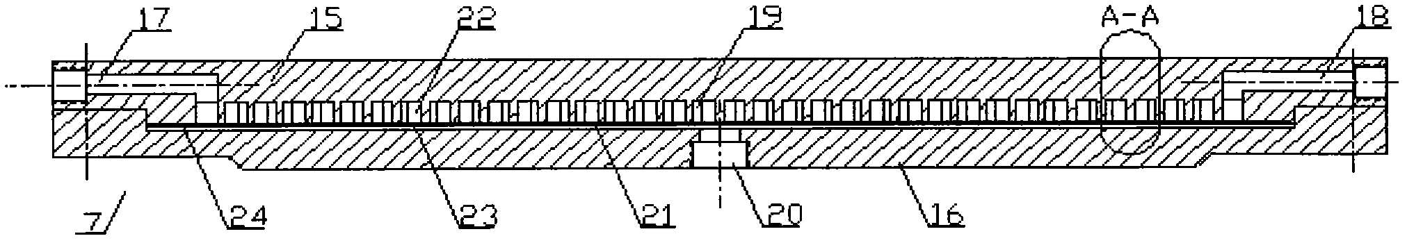
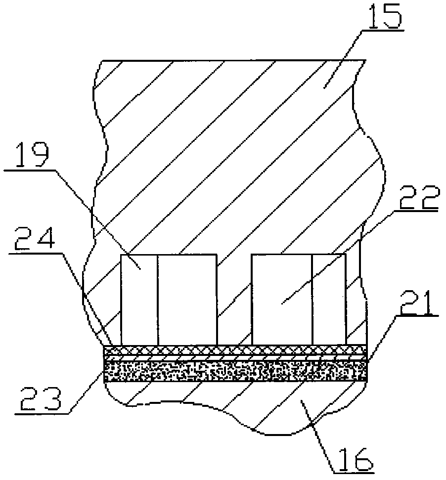
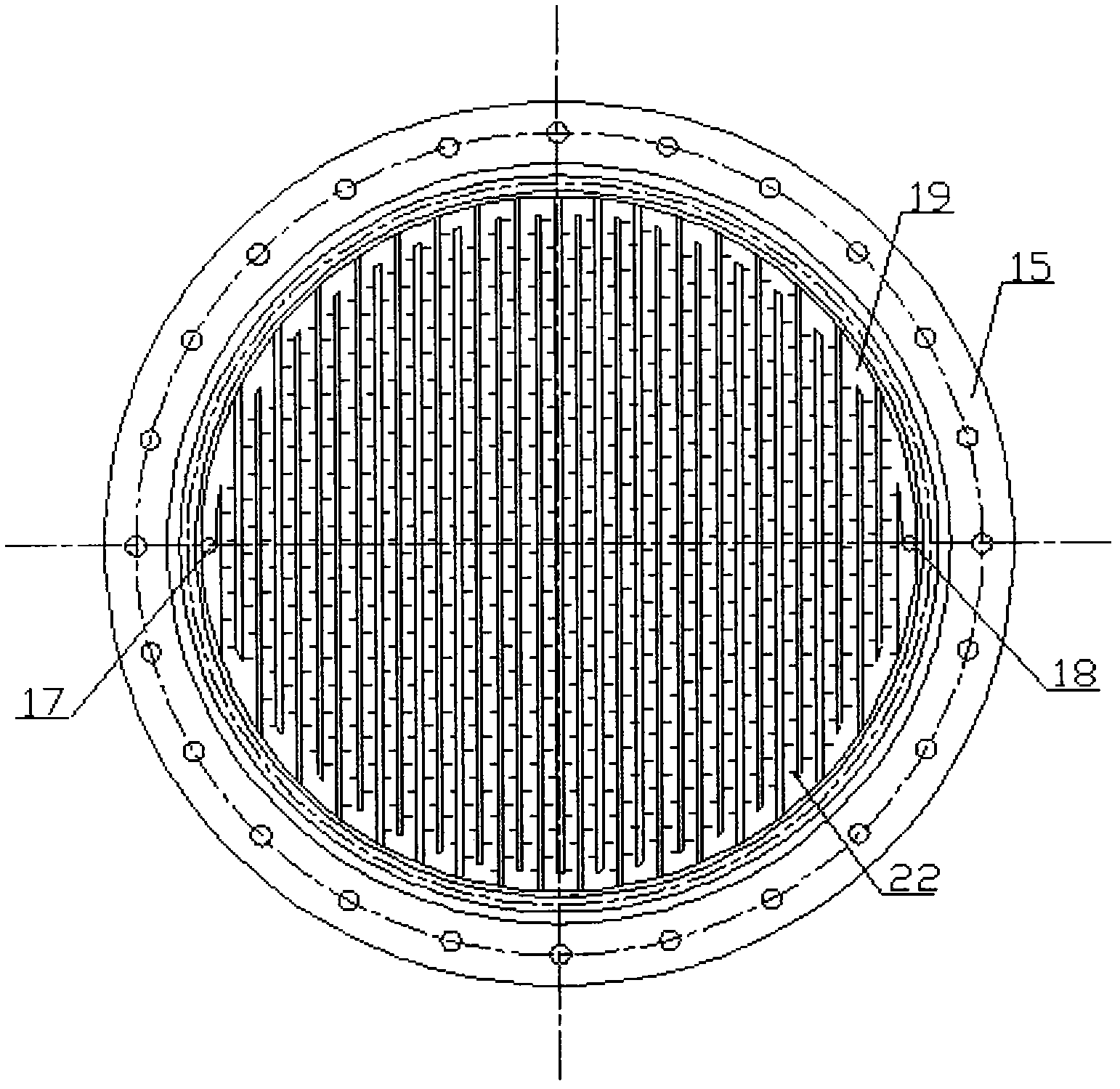
[0034] Such as figure 1 , the flat-panel turbulent dynamic membrane separation device 7 includes an upper cover plate 15 and a lower cover plate 16, and the upper and lower cover plates are fastened by bolts. combine figure 1 with figure 2 , the two ends of the upper cover plate 15 are provided with a liquid inlet 17 and a concentrated liquid port 18, and the upper cover plate 15 is provided with a zigzag groove 19 to form a reciprocating baffle flow channel, and the head and tail of the groove 19 are respectively connected with the liquid inlet 17 is connected with the dope port 18, if the disturbing flow part 22 is set in the groove 19, the spoiling part 22 can be disassembled freely, and the spoiling part 22 can adopt a spiral spoiling part, a baffle type spoiling part or a wave spoiling part. stream components, see Figure 4a with Figure 4b . The central position below the lower ...

Embodiment 2

[0039] Embodiment 2 membrane separation method

[0040] Such as Image 6 As shown, the raw water in the water inlet device 1 and the medicinal solution in the dosing device 3 are transported to the mixing device 6 through the water inlet pump 2 and the dosing pump 4 respectively, and the raw water and the medicinal solution complete the mixing process in the mixing device 6. After mixing The feed liquid enters the membrane separation device 7 through the liquid inlet 17 of the flat-panel turbulent dynamic membrane separation device 7, and flows through the surface of the filter screen 24 and the membrane 23 through the reciprocating zigzag flow channel formed by the groove 19, and the feed liquid Under the joint action of the filter screen 24, the reciprocating zigzag flow channel and the interfering flow member 22 added in the flow channel, the fluid generates strong turbulent flow, which hinders the adsorption and deposition of suspended particles and colloidal substances in...


PUM


Abstract

The present invention discloses a flat plate turbulence type dynamic membrane separation device. The device comprises an upper cover plate and a lower cover plate. Both ends of the upper cover plate are respectively provided with a liquid inlet and a concentrated liquid opening. The upper cover plate is provided with a zigzag groove, which forms a reciprocating baffling flow type flow channel. The head and the tail of the groove are respectively connected with the liquid inlet and the concentrated liquid opening. A plurality of turbulence components are arranged inside the groove. A filtrate outlet is arranged below the lower cover plate or on the side surface of the lower cover plate. A support plate is arranged above the lower cover plate. A membrane is arranged above the support plate. A screen is arranged above the membrane. The present invention further discloses a membrane separation method, wherein the flat plate turbulence type dynamic membrane separation device is combined with the coagulation process by the method. The flat plate turbulence type dynamic membrane separation device of the present invention has characteristics of simple structure, effective release of membrane pollution, flexible operation and control, easy maintenance and low energy consumption. With the membrane separation method of the present invention, the membrane pollution can be effectively released, and the effluent quality can be significantly improved, such that the effluent is applicable for the engineering application.

Description

technical field [0001] The invention relates to a membrane separation device, in particular to a flat plate turbulence type dynamic membrane separation device, and also relates to a membrane separation method. Background technique [0002] Membrane fouling is one of the main factors affecting the wide application of membrane separation technology. The pollution of pollutants on the membrane surface has a process. At first, the pollutants are adsorbed and blocked in the membrane pores. As the filtration process progresses, under the action of concentration polarization, the pollutants gradually deposit on the membrane surface to form a gel layer. , and then gradually form a filter cake layer. Adopting appropriate filtration methods, optimizing operating conditions, and pretreatment of feed liquid are effective ways to alleviate membrane fouling. [0003] Compared with dead-end filtration (or "terminal filtration"), dynamic filtration can significantly alleviate membrane fou...

Claims


Application Information

Patent Timeline
Patent Type & Authority Patents(China)
IPC IPC(8): B01D63/08
Inventor 张忠国吴月程言君何沛然刘丹荣立明赵可卉任晓晶
Owner ENVIRONMENTAL PROTECTION RES INST OF LIGHT IND
Why Eureka
Try Eureka