Material disc of automatic material feeding device

A technology of automatic feeding and trays, applied in vibrating conveyors, conveyors, transportation and packaging, etc., can solve problems such as difficult sorting, manual sorting, loose exhaust pipes, etc., to reduce production costs, improve work efficiency, improve The effect of dynamic performance

Inactive Publication Date: 2012-04-25
GUANGDONG GALANZ GRP CO LTD
View PDF5 Cites 11 Cited by
  • Summary
  • Abstract
  • Description
  • Claims
  • Application Information

AI Technical Summary

Problems solved by technology

The traditional operation method is to manually insert the exhaust pipe into the exhaust seat, and press the exhaust pipe hard, which requires a lot of workers to work by hand. This operation method greatly increases the cost of labor, and cannot guarantee the magnetic To control the quality of the exhaust seat inserted into the exhaust pipe, problems such as loose exhaust pipes and different insertion depths often occur. To solve the problems, people hope to develop an installation machine for automatically inserting exhaust pipes, which can carry out automated production. The production line can have multiple material racks at the same time, reducing labor costs and improving product quality; when developing an installation machine for automatically inserting exhaust pipes, it is difficult to arrange the exhaust pipes of microwave ovens, and it is still necessary to manually arrange and determine the direction; for this It is urgent to invent an automatic feeding device that can adjust the speed, automatically sort and determine the direction

Method used


Image

  • Material disc of automatic material feeding device
  • Material disc of automatic material feeding device
  • Material disc of automatic material feeding device

Examples


Embodiment Construction

[0017] The invention will be described in further detail below in conjunction with the accompanying drawings.

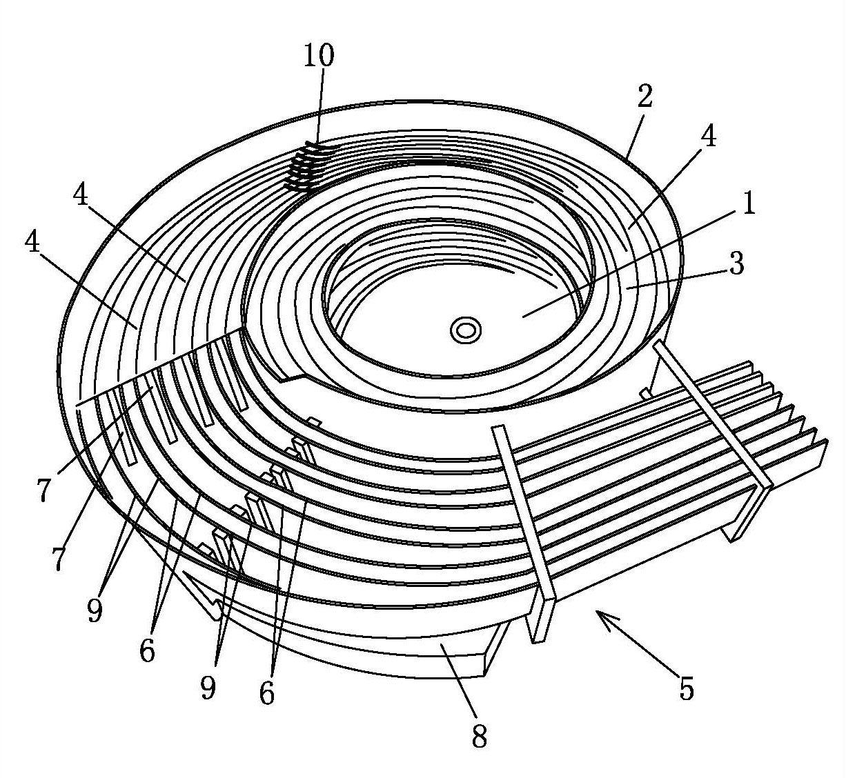
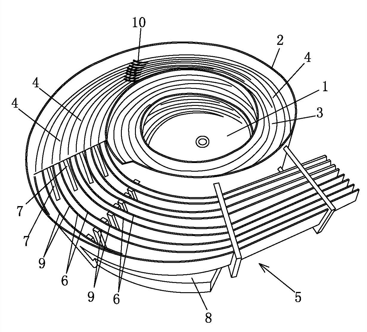
[0018] Such as figure 1 with figure 2 As shown, a feeding tray of an automatic feeding device includes a tray surface 1 and a side wall 2 surrounding the tray surface 1. A spirally rising feeding track 3 is arranged on the inner side of the side wall 2, and the feeding end of the feeding track 3 is located at the bottom of the tray surface 1. At the lower part, the surface of the feeding track 3 is provided with a plurality of partitions 4 side by side. The discharge end of the feeding track 3 is connected to the monolithic rail 5 , and the monolithic rail 5 includes a hanging path 6 and a blanking path 9 . The feeding port of hanging road 6 is connected with the discharging port of every other road in one-to-one correspondence, and blanking road 9 is arranged between adjacent hanging roads 6 . The periphery of the monolith track 5 is provided with a collection gr...


PUM


Abstract

The invention relates to a material disc of an automatic material feeding device, which comprises a disc surface and a side wall around the disc surface, wherein the inner side of the side wall is provided with a spirally-risingen charge track, a charge end of the charge track is arranged at a lower place of the disc surface, a plurality of isolating ways are arranged on the surface of the charge track side by side, a discharge end of the charge track is connected with an integrated material track, the integrated material track comprises a plurality of suspending ways and a plurality of material falling ways, a plurality of charge openings of the suspending ways and a plurality of discharge openings of the isolating ways are correspondingly connected with one another one by one, the material falling ways are arranged among the adjoining suspending ways, the charge track or the integrated material track is provided with a sensor capable of sensing the moving speed of spare parts, and the sensor is connected with a voltage controller by a signal controller. The periphery of the integrated material track is provided with a collecting groove, the collecting groove is connected with the material disc into a whole body, and the collecting groove is communicated with an inner cavity of the material disc by an opening on the side wall of the collecting groove. The material disc has the advantages of being adjustable in speed, and autonomic in sequencing for the spare parts.

Description

technical field [0001] The invention relates to an automatic production of spare parts of a microwave oven, in particular to an automatic feeding tray with multiple feeding racks. Background technique [0002] Parts and accessories for microwave ovens, such as the exhaust pipe of microwave ovens, need to insert exhaust pipes into the exhaust seats during processing. The traditional operation method is to manually insert the exhaust pipe into the exhaust seat, and press the exhaust pipe hard, which requires a lot of workers to work by hand. This operation method greatly increases the cost of labor, and cannot guarantee the magnetic To control the quality of the exhaust seat inserted into the exhaust pipe, problems such as loose exhaust pipes and different insertion depths often occur. To solve the problems, people hope to develop an installation machine for automatically inserting exhaust pipes, which can carry out automated production. The production line can have multiple ...

Claims


Application Information

Patent Timeline
Patent Type & Authority Applications(China)
IPC IPC(8): B65G27/02B65G27/24B65G27/32
Inventor 张文亮
Owner GUANGDONG GALANZ GRP CO LTD
Why Eureka
Try Eureka