Heat pump system and flow measuring method thereof

A technology of heat pump system and flowmeter, which is applied in the direction of heat pump, application of electromagnetic flowmeter to detect fluid flow, volume/mass flow generated by electromagnetic effect, etc., which can solve the problem of reduced cooling capacity, increased user cost, and failure to meet user requirements And other issues

Inactive Publication Date: 2012-04-25
苏宇贵
View PDF3 Cites 3 Cited by
  • Summary
  • Abstract
  • Description
  • Claims
  • Application Information

AI Technical Summary

Problems solved by technology

[0002] At present, the charging amount of the heat exchange working medium in the heat pump system (such as air conditioner or heat pump water heater) is generally calculated through the thermal calculation of the heat pump system, but there is often a certain deviation between the calculated value and the actual demand of the heat pump system, and the replacement The deviation of the charging amount of thermal working medium will have a certain impact on the actual operation of the heat pump system. For example, when the charging amount is too small, the cooling capacity will decrease, which cannot meet the user's requirements; when the charging amount is too high, the power will be reduced. Consumption increases, increasing the user's use cost, which is not conducive to energy saving
[0003] As far as the current situation is concerned, experienced designers and new product trial-manufacturers often need to take corresponding technical measures and make precise adjustments to the operation process of new products in order to obtain the correct charging amount of heat exchange working fluid. It is extremely inconvenient to use, so it is necessary to improve the existing structure in order to more conveniently measure the flow rate of the heat exchange working medium

Method used


Image

  • Heat pump system and flow measuring method thereof
  • Heat pump system and flow measuring method thereof
  • Heat pump system and flow measuring method thereof

Examples


Embodiment Construction

[0021] Embodiments of the present invention will be described in detail below.

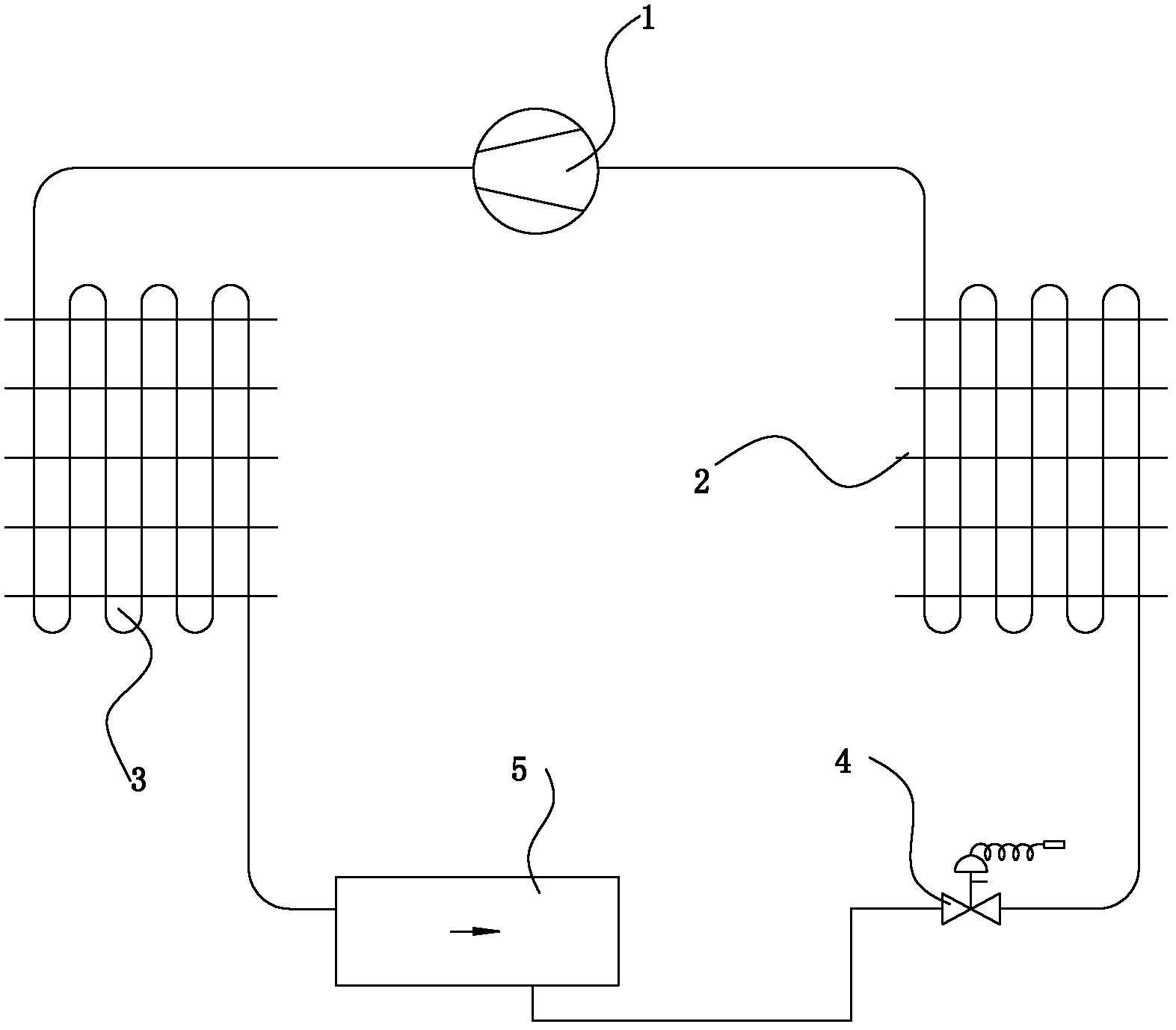
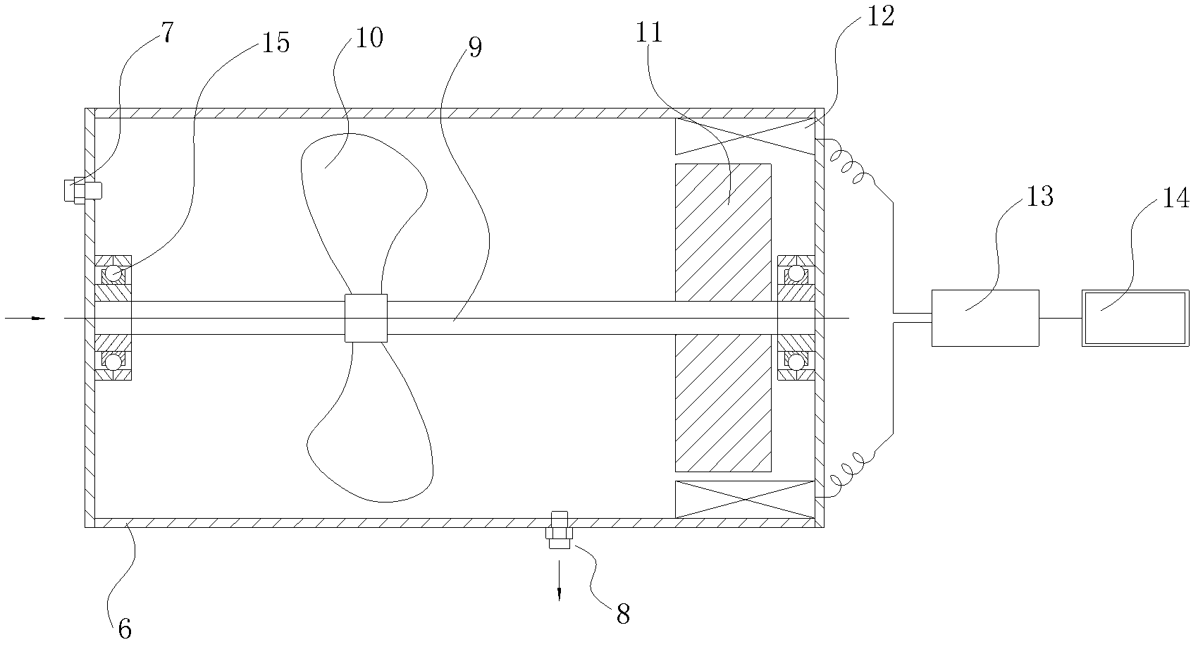
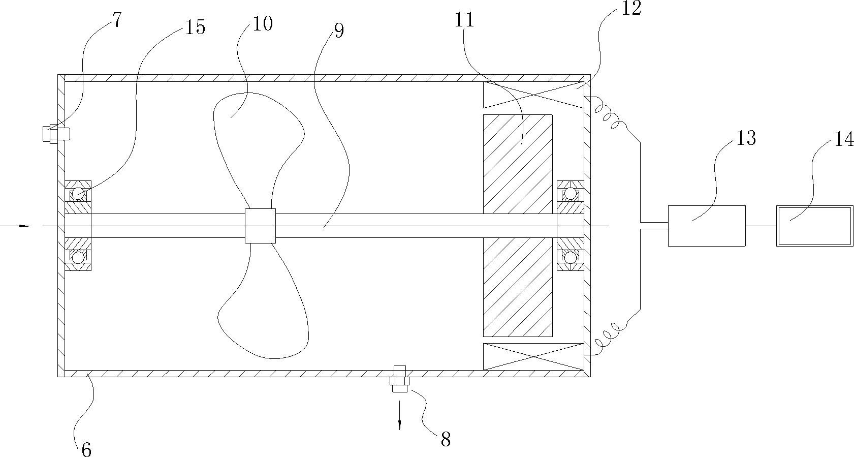
[0022] Such as figure 1 , figure 2 As shown, a heat pump system includes a first heat exchanger 2, a second heat exchanger 3, a compressor 1 and a throttling element 4, a first heat exchanger 2, a second heat exchanger 3, a compressor 1 and The throttling elements 4 are connected by connecting pipes to form a heat exchange working medium circulation circuit, and a heat exchange working medium flow meter 5 is arranged on the heat exchange working medium circulation circuit, and the heat exchange working medium flow meter 5 includes a housing 6 , the housing 6 is provided with an inlet 7 and an outlet 8, and a rotating shaft 9 is arranged inside the housing 6, and an impeller 10 is arranged on the rotating shaft 9, and the impeller 10 is located between the inlet 7 and the outlet 8, and a magnetic pole is arranged on the rotating shaft 9 11. A coil 12 corresponding to the magnetic pole 11 is prov...


PUM


Abstract

The invention discloses a heat pump system comprising a first heat exchanger, a second heat exchanger, a compressor and a throttling element which are connected through connecting pipes to form a heat exchange working medium circulation loop, wherein a heat exchange working medium flow meter is arranged on the heat exchange working medium circulation loop, the heat exchange working medium flow meter comprises a shell, an inlet and an outlet are arranged on the shell, a rotating shaft is arranged in the shell, an impeller is arranged on the rotating shaft and between the inlet and the outlet, a magnetic pole is arranged on the rotating shaft, a coil corresponding to the magnetic pole is arranged on the shell, and the coil is electrically connected with a signal analyzing and processing device. The heat pump system disclosed by the invention can more conveniently measure the flow rate of the heat exchange working medium in the heat pump system, and has important directive significance on mass production of new products such as air conditioner or heat pump water heaters and the like.

Description

technical field [0001] The invention relates to a heat pump system and a flow measurement method thereof. Background technique [0002] At present, the charging amount of the heat exchange working medium in the heat pump system (such as air conditioner or heat pump water heater) is generally calculated through the heat of the heat pump system. However, there is often a certain deviation between the calculated value and the actual demand of the heat pump system. The deviation of the charging amount of thermal working medium will have a certain impact on the actual operation of the heat pump system. For example, when the charging amount is too small, the cooling capacity will decrease, which cannot meet the user's requirements; when the charging amount is too high, the power will be reduced. Increased consumption will increase the user's use cost, which is not conducive to energy saving. [0003] As far as the current situation is concerned, experienced designers and new prod...

Claims


Application Information

Patent Timeline
Patent Type & Authority Applications(China)
IPC IPC(8): F25B30/02G01F1/58
Inventor 苏宇贵
Owner 苏宇贵
Why Eureka
Try Eureka