Nondestructive inductor current detection circuit applicable to high-frequency step-down type voltage converter
A voltage converter, inductor current technology, applied in the direction of measuring current/voltage, instruments, measuring devices, etc., can solve the problems of current detection cost and power consumption increase, limitation, difficulty in inductor current detection, etc.
- Summary
- Abstract
- Description
- Claims
- Application Information
AI Technical Summary
Problems solved by technology
Method used
Image
Examples
Embodiment Construction
[0014] Hereinafter, the present invention will be further described in detail based on the drawings and design examples.
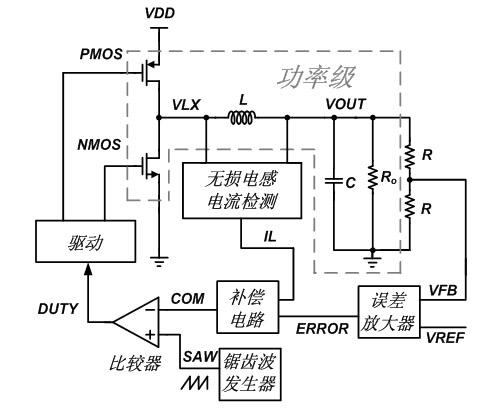
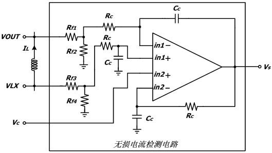
[0015] The invention designs a lossless inductor current detection circuit applied to a high-frequency step-down voltage converter. The typical application structure of this circuit is as follows figure 1 Shown. The high-frequency step-down DC voltage converter is composed of power stage and control stage circuits. The power stage consists of the power tube PMOS, NMOS, filter inductor L, filter capacitor C, and load resistance R o Composition; The control stage is composed of a lossless inductor current detection circuit, an error amplifier, a compensation circuit, a sawtooth wave generator, and a compensation circuit. The control stage circuit detects the difference between the inductor current IL and the reference voltage VREF and the output feedback voltage VFB through the lossless inductor current detection circuit. The difference ERROR amplified by the ...
PUM
 Abstract
Description
Claims
Application Information
 - R&D
- Intellectual Property
- Life Sciences
- Materials
- Tech Scout
- Unparalleled Data Quality
- Higher Quality Content
- 60% Fewer Hallucinations
Browse by: Latest US Patents, China's latest patents, Technical Efficacy Thesaurus, Application Domain, Technology Topic, Popular Technical Reports.
© 2025 PatSnap. All rights reserved.Legal|Privacy policy|Modern Slavery Act Transparency Statement|Sitemap|About US| Contact US: help@patsnap.com


