Method for determining low-temperature working stress limit of aircraft anti-skid braking control box

A work stress, anti-skid braking technology, applied in measuring devices, instruments, measuring electricity and other directions, can solve problems such as unrealistic data

Inactive Publication Date: 2012-04-25
XIAN AVIATION BRAKE TECH
View PDF4 Cites 16 Cited by
  • Summary
  • Abstract
  • Description
  • Claims
  • Application Information

AI Technical Summary

Problems solved by technology

And at present, the low-temperature working stress limit test of other foreign electronic products is carried out under non-working conditions. The method of only applying environmental stress without applying

Method used


Image

  • Method for determining low-temperature working stress limit of aircraft anti-skid braking control box

Examples


Embodiment 1

[0027] This embodiment is a test for determining the low-temperature working stress limit of the first type of control box, and the test samples are 2 sets of control boxes. The design of the test sample has been improved for the low temperature problem in the development test.

[0028] The test of this embodiment uses a reliability enhancement test box model UHS1200, a digital multimeter, a signal source and an oscilloscope.

[0029] The concrete process of this embodiment is:

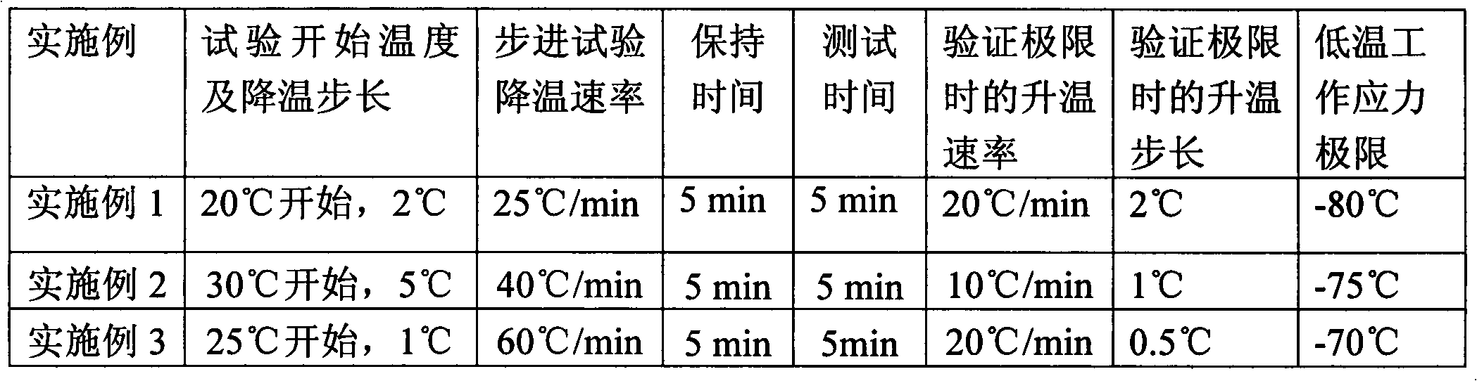
[0030] Step 1, determine the test parameters. The test parameters include test temperature starting point, cooling step size and cooling rate. The cooling step is not greater than 5°C, and the smaller the more accurate, the starting point of the test temperature in this embodiment is 20°C, the cooling step is 2°C, and the cooling rate is 25°C / min.

[0031] Step 2, heating the test sample. Install the 2 sets of test samples on the moving coil in the strengthening test box with fixtures. Heat the t...

Embodiment 2

[0036] This embodiment is a test for determining the low-temperature working stress limit of the second type of control box, and the test sample is a set of control boxes. The design of the test sample has been improved for the low temperature problem in the development test.

[0037] The test of this embodiment uses a reliability enhancement test box model UHS1200, a digital multimeter, a signal source and an oscilloscope.

[0038] The concrete process of this embodiment is:

[0039] Step 1, determine the test parameters. The test parameters include test temperature starting point, cooling step size and cooling rate. The cooling step is not greater than 5°C, and the smaller the more accurate, the starting point of the test temperature in this embodiment is 30°C, the cooling step is 5°C, and the cooling rate is 40°C / min.

[0040] Step 2, heating the test sample. One set of test samples is installed on the moving coil in the strengthening test box with the fixture. Heat th...

Embodiment 3

[0045] This embodiment is a test for determining the low-temperature working stress limit of the third type of control box, and the test sample is a set of control boxes. The design of the test sample has been improved for the low temperature problem in the development test.

[0046] The test of this embodiment uses a reliability enhancement test box model UHS1200, a digital multimeter, a signal source and an oscilloscope.

[0047] The concrete process of this embodiment is:

[0048] Step 1, determine the test parameters. The test parameters include test temperature starting point, cooling step size and cooling rate. The cooling step is not greater than 5°C, and the smaller the more accurate, the starting point of the test temperature in this embodiment is 25°C, the cooling step is 1°C, and the cooling rate is 60°C / min.

[0049] Step 2, heating the test sample. One set of test samples is installed on the moving coil in the strengthening test box with the fixture. Heat the...


PUM


Abstract

The invention discloses a method for determining low-temperature working stress limit of an aircraft anti-skid braking control box. The low-temperature working stress limit of the control box is determined by applying low-temperature stress to the control box in a stepped mode with a low-temperature step environment stress test method. In the method, the test time for testing the low-temperature working stress limit of the control box is 6-8 hours; the temperature drop step length is 1-5 DEG C; the temperature drop rate is 25-60 DEG C/minute; the temperature is kept for 5 minutes each time after the temperature is dropped to a specified value; the time for temperature balance of the control box is reserved; then performance test is performed, and the test time is 5 minutes; and the sum oftemperature keeping time at each step is 10 minutes. The low-temperature working stress limit of a sample is obtained according to such stepped temperature drop test method. Since the failure of the control box occurs in a working process, application of working stress in the test process of dropping the temperature by using the stepped method more facilitates excitation and observation of the failure; and a test method capable of quickly determining the low-temperature failure hidden trouble of the control box and determining the low-temperature working stress limit of the control box is formed.

Description

technical field [0001] The invention relates to the field of electronic products of a landing gear control system of a transport aircraft. Specifically, it is an aircraft anti-skid brake control box, referred to as the control box. Background technique [0002] The control box is the control unit in the aircraft electric anti-skid braking system, which is designed with the functions of take-off line braking, anti-skid function during landing braking, grounding protection function during landing, inter-wheel protection of left and right landing gear wheels during landing, etc. A variety of functions, any one of which does not meet the design requirements is a failure. In the present invention, the working performance of the control box refers to the quantitative requirements of the above-mentioned various functions. [0003] In order to ensure the reliability and safety requirements of the control box, the high-accelerated life test technology is used internationally to sti...

Claims


Application Information

Patent Timeline
IPC IPC(8): G01R31/00
Inventor 乔建军田广来黄智商海东张谦刘忠平
Owner XIAN AVIATION BRAKE TECH
Why Eureka
Try Eureka