
Methods for distributing reactive power compensation capacity and switching branch circuits of passive filter

A passive filter and filtering branch technology, applied in reactive power compensation, reactive power adjustment/elimination/compensation, harmonic reduction devices, etc., can solve poor reactive power regulation performance, current or voltage waveform distortion, short Avoid short-time harmonic amplification and other problems, achieve the effects of avoiding short-time harmonic amplification, reasonable distribution of compensation amount, and good dynamic compensation performance

Active Publication Date: 2012-04-25
BEIJING TIANDI HUATAI MINING MANAGEMENT CO LTD
View PDF0 Cites 24 Cited by
  • Summary
  • Abstract
  • Description
  • Claims
  • Application Information

AI Technical Summary

Problems solved by technology

At present, most of the branch reactive capacity distribution of passive filters adopts the average distribution method, or simply distributes according to the magnitude of each harmonic current. The branch circuit combination method is simple, and the reactive power adjustment performance is poor. When the system load changes, it cannot Completely guarantee the system power quality is qualified; the filter switching operation is simply input from low order to high order when input, and exit from high order to low order when exiting, which may cause short-term harmonics during the switching process of the filter operation mode. Wave amplification, current or voltage waveform distortion, system power factor over limit, system protection malfunction, etc., affect the safe and economical operation of the system and equipment

Method used


Image

  • Methods for distributing reactive power compensation capacity and switching branch circuits of passive filter
  • Methods for distributing reactive power compensation capacity and switching branch circuits of passive filter
  • Methods for distributing reactive power compensation capacity and switching branch circuits of passive filter

Examples


Embodiment 1

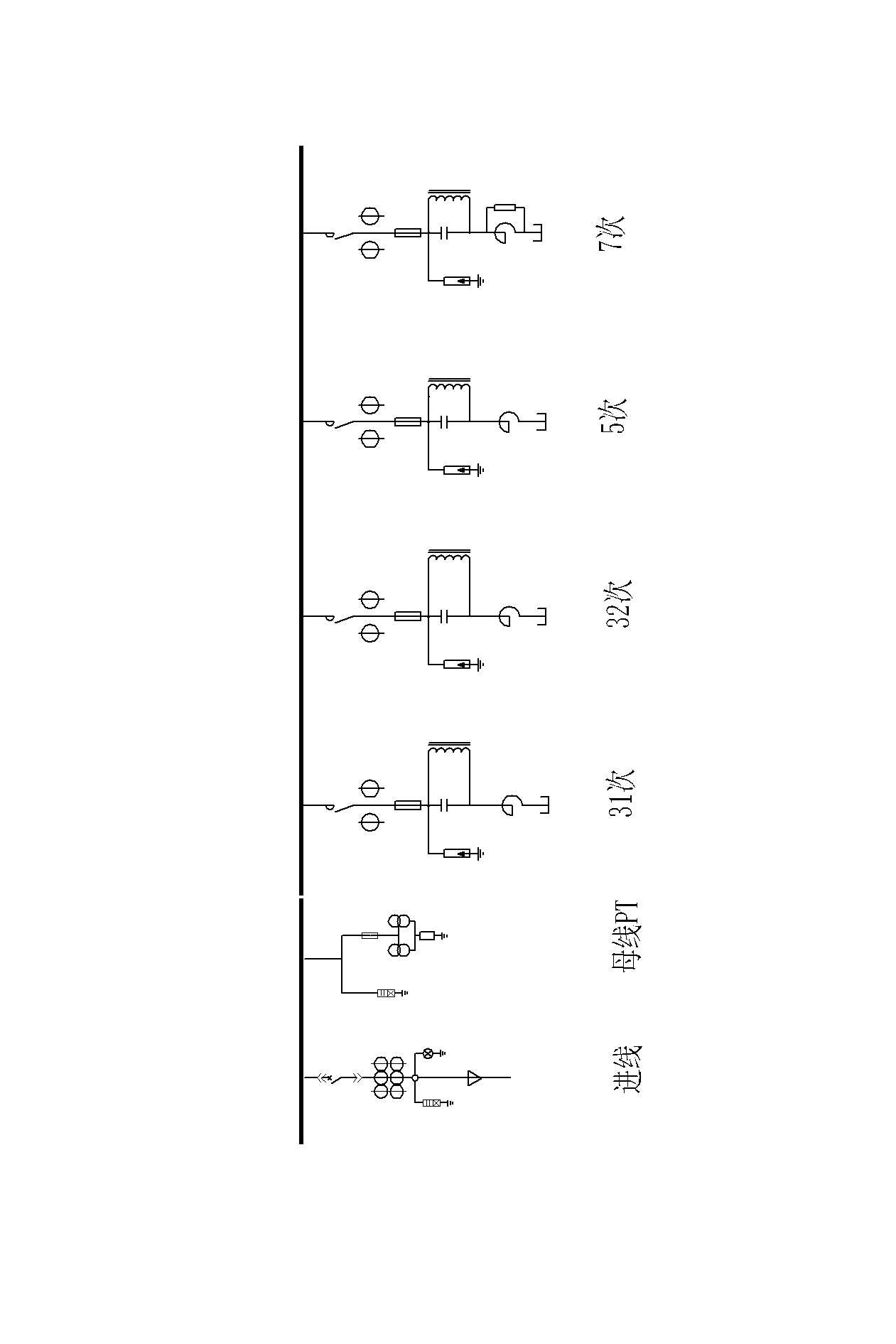
[0034] This embodiment is a method for distributing the reactive power compensation capacity of a passive filter. The passive filter designed according to the method has a plurality of filter branches, and the filter branches are composed of switching switches, capacitors, and resistors. , reactor and other components, such as figure 1 shown. The secondary control, measurement and protection loops of each filtering branch are connected with the controller.

[0035] The filter described in this embodiment is mainly used in a three-phase AC power supply system. The filter branch circuit adopts star connection, the neutral point is not grounded, and the switching switch, capacitor and reactor in the branch circuit are connected in series. A resistor and a capacitor are connected in parallel at both ends of the filter to form a high-pass or C-type filter branch, or no resistor or capacitor is connected in parallel to form a single-tuned filter branch. The number of filtering bra...

Embodiment 2

[0060] This embodiment is an improvement of the first embodiment, and is a refinement of the step of calculating the load rate of the filtering branch described in the first embodiment. The step of calculating the load rate of the filtering branch described in this embodiment includes the following sub-steps:

[0061] Calculate the load factor of the lowest harmonic filter branch : Take the reactive power compensation amount and the total reactive power compensation amount calculated when the monthly minimum load of the mine is taken If the reactive power compensation amount of the lowest harmonic filtering branch is relatively large, it can be split into two lowest harmonic filtering branches according to the ratio of reactive compensation amount 2:1;

[0062] Calculation of load ratios to other filter branches , using the formula

[0063]

[0064] is the total number of harmonics, is the harmonic order, for The harmonic sequence number corresponding to the s...

Embodiment 3

[0067] This embodiment is a refinement of the above-mentioned embodiment, and is a refinement of the reactive power compensation amount of the n-time filter branch in the step of calculating the component parameters of each filter branch described in the above-mentioned embodiment. The reactive power compensation amount of the n-time filter branch in the step of calculating the component parameters of each filter branch described in the reactive compensation amount described in this embodiment Multiply by a factor of 1.04-1.13.

[0068] The reactance rate is the ratio of the reactance value of the series filter branch to the capacitive reactance value of the capacitor bank, which is used express. In the filter branch, the ratio of the branch loss compensation capacity to the branch capacitance compensation capacity is equal to the value of the reactance rate. The reactive power compensation capacity allocated by the filter branch refers to the effective compensation capaci...


PUM


Abstract

The invention relates to methods for distributing the reactive power compensation capacity and switching branch circuits of a passive filter. In the method, the passive filter is provided with a plurality of filter branch circuits; and each filter branch circuit consists of a switching relay, a capacitor, a resistor and a reactor. The method for distributing the reactive power compensation capacity of the passive filter comprises the following steps of: calculating a total reactive power compensation quantity; calculating the compensation capacity of the filter branch circuits; and calculating element parameters of the respective filter branch circuits. The passive filter designed by using the method for distributing the reactive power compensation capacity of the passive filter performs reactive power compensation and filter suppression, and the reactive power compensation capacity of the respective filter branch circuits compenhensively considers a load running characteristic and harmonic source current, so that the compensation quantities of the filter branch circuits are more reasonable; therefore, the passive filter can run more flexibly and has higher dynamic compensation property.

Description

technical field [0001] The invention relates to a reactive power compensation capacity distribution and branch circuit switching method of a passive filter, a parameter design method and an operation control method of a complete set of electrical equipment, and a method guaranteed to be applied to reactive power compensation and harmonics in a power supply system. The suppressed passive filter complete set has a design method of good dynamic performance and a method of realizing automatic safety action of the device. Background technique [0002] The harmonic sources of modern coal mine power supply system mainly include frequency conversion belt conveyor, shearer frequency conversion device, hoist electric control system, etc., generally 3, 5, 7, 11 harmonics, and the coal mine load is stepped due to the characteristics of coal mine production There is no serious unbalance of three-phase voltage and current caused by electric arc furnace load. Harmonic control and reactive...

Claims


Application Information

Patent Timeline
IPC IPC(8): H02J3/18H02J3/01
CPCY02E40/30Y02E40/40
Inventor 石晓军刘文岗
Owner BEIJING TIANDI HUATAI MINING MANAGEMENT CO LTD
Learn More