
Accelerating device of rising edge and falling edge of current pulse and accelerating method thereof

A technology of current pulse and acceleration device, which is applied in the direction of electric pulse generator circuit and active components to generate pulses, etc., can solve the problems of complicated transmitter hardware, and achieve the effect of smoothing the positive and negative peak segments.

Inactive Publication Date: 2012-04-25
JILIN UNIV
View PDF3 Cites 10 Cited by
  • Summary
  • Abstract
  • Description
  • Claims
  • Application Information

AI Technical Summary

Problems solved by technology

[0004] Among the above two schemes, the first requires increasing the voltage of the DC power supply, and the second requires providing an auxiliary DC power supply. These two schemes add too much hardware for the purpose of accelerating the rising and falling edges, making the transmitter hardware getting complicated

Method used


Image

  • Accelerating device of rising edge and falling edge of current pulse and accelerating method thereof
  • Accelerating device of rising edge and falling edge of current pulse and accelerating method thereof
  • Accelerating device of rising edge and falling edge of current pulse and accelerating method thereof

Examples


Embodiment Construction

[0041] Below in conjunction with accompanying drawing and embodiment, the present invention is described in further detail:

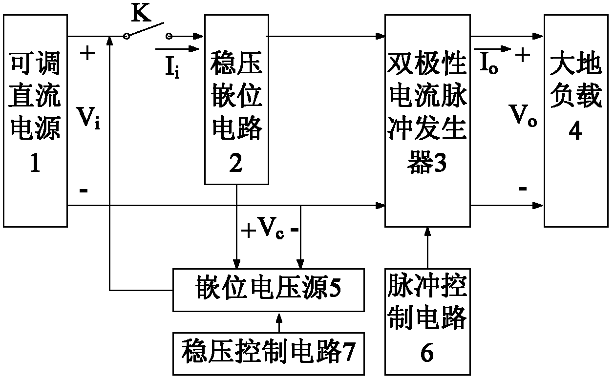
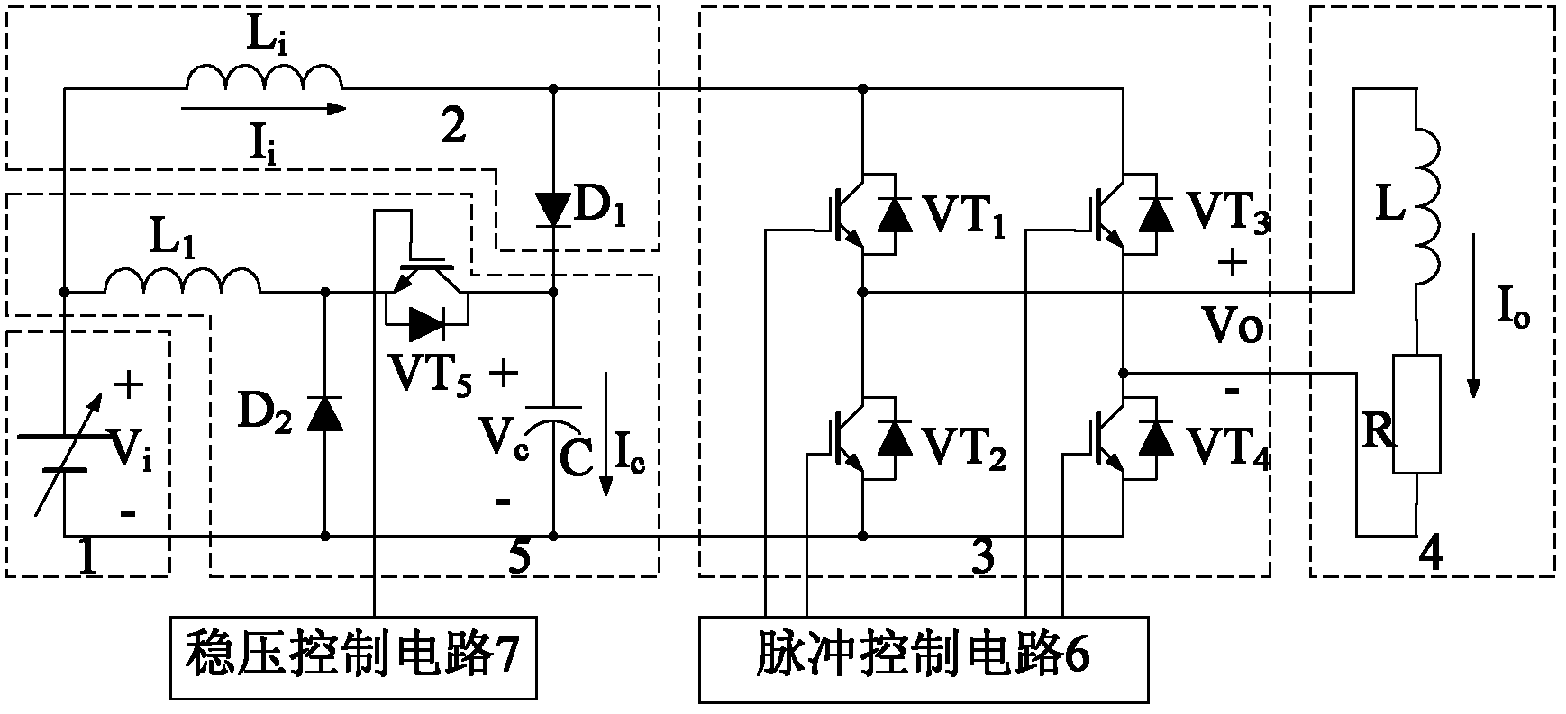
[0042] The current pulse rising and falling edge acceleration device is connected by the positive pole of the controllable DC power supply 1 to the voltage regulator clamping circuit 2, the bipolar current pulse generator 3 and the positive pole of the earth load 4 through the switch K. The controllable DC power supply The negative pole of 1 is connected to the negative pole of the earth load 4 through the bipolar current pulse generator 3, the clamping voltage source 5 is connected to the positive pole of the controllable DC power supply 1, and the negative pole of the controllable DC power supply 1 is connected to the clamping voltage source 5. The voltage-stabilizing clamping circuit 2 is connected to the clamping voltage source 5 , the voltage-stabilizing control circuit 7 is connected to the clamping voltage source 5 , and the pulse control circuit ...


PUM


Abstract

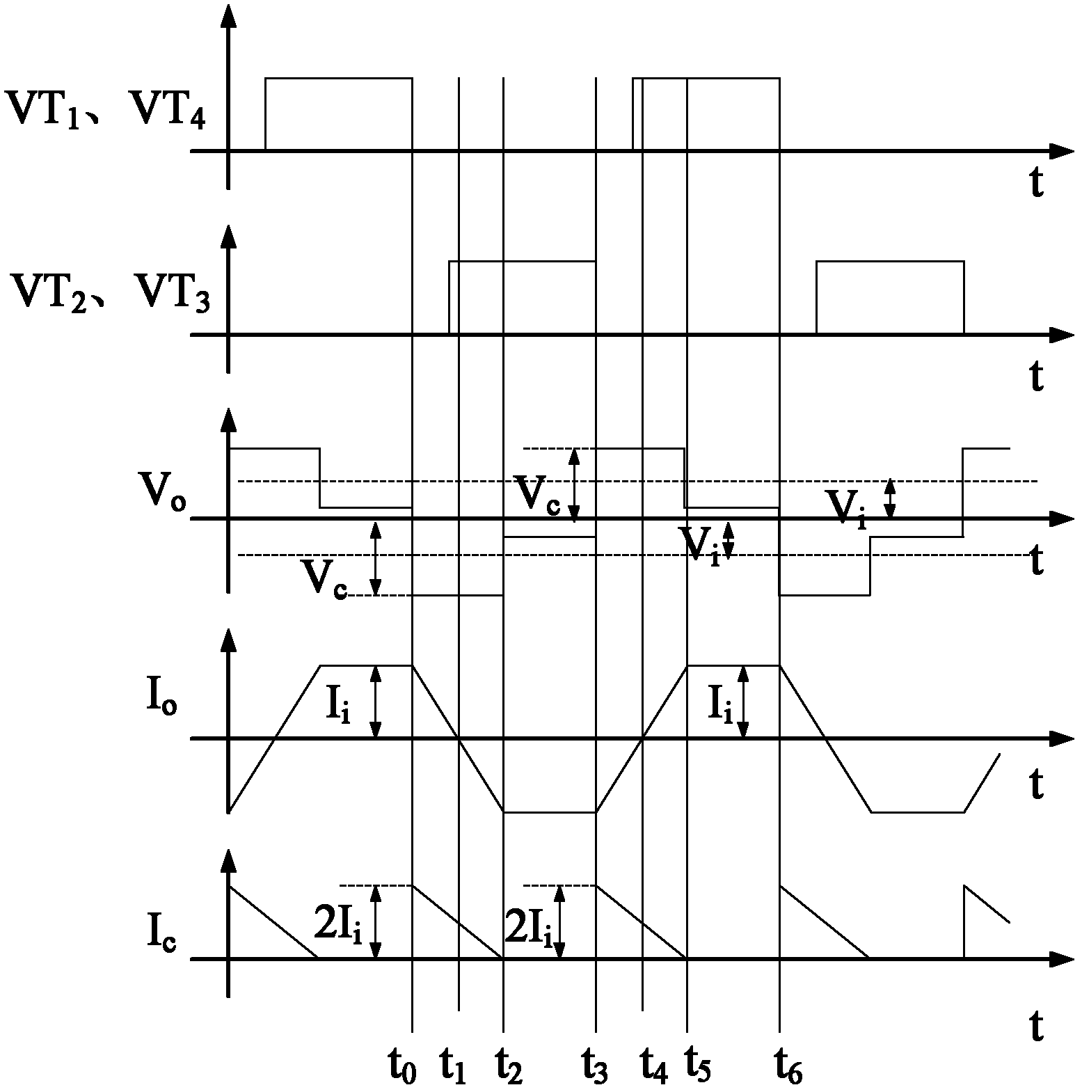
The invention relates to an accelerating device of a rising edge and a falling edge of a current pulse and an accelerating method thereof. The accelerating device is characterized in that: an anode of a controllable direct current source is connected with a voltage stabilization clamping circuit, a bipolar current pulser and an anode of an earth load through a switch K; a cathode of the controllable direct current source is connected with a cathode of the earth load through the bipolar current pulser; and a pulse control circuit is connected with the bipolar current pulser; therefore, the accelerating device is formed. Beneficial effects of the invention are as follows: first, the voltage stabilization clamping circuit can generate high voltages in a bootstrapped mode on a capacitor C of a clamping voltage source, and then a rising edge and a falling edge of a current pulse are accelerated by using the high voltages of the capacitor C; therefore, there is no need to improve a direct current source voltage or provide an auxiliary power source; second, the output of the controllable direct current source is connected with the bipolar current pulser through an inductor Li of the voltage stabilization clamping circuit and the inductor Li plays a role in current stabilization of a forward peak value segment and a negative peak value segment of a current pulse Io (t), so that the forward peak value segment and the negative peak value segment of the current pulse Io (t) are smooth.

Description

Technical field: [0001] The invention relates to an electrical geophysical prospecting instrument, in particular to an acceleration device and an acceleration method for a current pulse rising edge and falling edge of a load with a load resistance value of several tens of Ω and an inductance value of several mH. Background technique: [0002] For the controllable source audio frequency magnetotelluric method (CSAMT), since the distance between the transmitter and the receiver is 5-10km, in order to make the signal-to-noise ratio of the signal collected by the receiver high, it is necessary for the transmitter to provide the ground load with the highest possible signal-to-noise ratio. Emission current; for the induced polarization method (IP), in order to obtain the polarizability of the earth more accurately, the rising and falling edges of the current pulse generated by the transmitter need to be as short as possible, and the positive peak and negative Be as smooth as possi...

Claims


Application Information

Patent Timeline
IPC IPC(8): H03K3/021
Inventor 林君薛开昶周逢道于生宝吴勇刘长胜
Owner JILIN UNIV
Learn More