Magnetoelectronic angle sensor, in particular a reluctance resolver

An angle sensor, electromagnetic technology, applied in the direction of using electric/magnetic devices to transmit sensing components, converting sensor output, using electromagnetic means, etc., can solve the problems of measurement accuracy influence, tolerance, complex assembly methods, etc., to achieve the effect of increasing accuracy

Active Publication Date: 2012-04-25
TYCO ELECTRONICS BELGIUM EC
View PDF5 Cites 21 Cited by
  • Summary
  • Abstract
  • Description
  • Claims
  • Application Information

AI Technical Summary

Problems solved by technology

However, most known reluctance resolver configurations have a disadvantage: the configuration of the windings on the stator results in a relatively complex assembly method
Also, reluctance resolvers in which the change in reluctance is achieved by a golf club-shaped or kidney-shaped rotor, where th...

Method used


Image

  • Magnetoelectronic angle sensor, in particular a reluctance resolver
  • Magnetoelectronic angle sensor, in particular a reluctance resolver
  • Magnetoelectronic angle sensor, in particular a reluctance resolver

Examples


Embodiment Construction

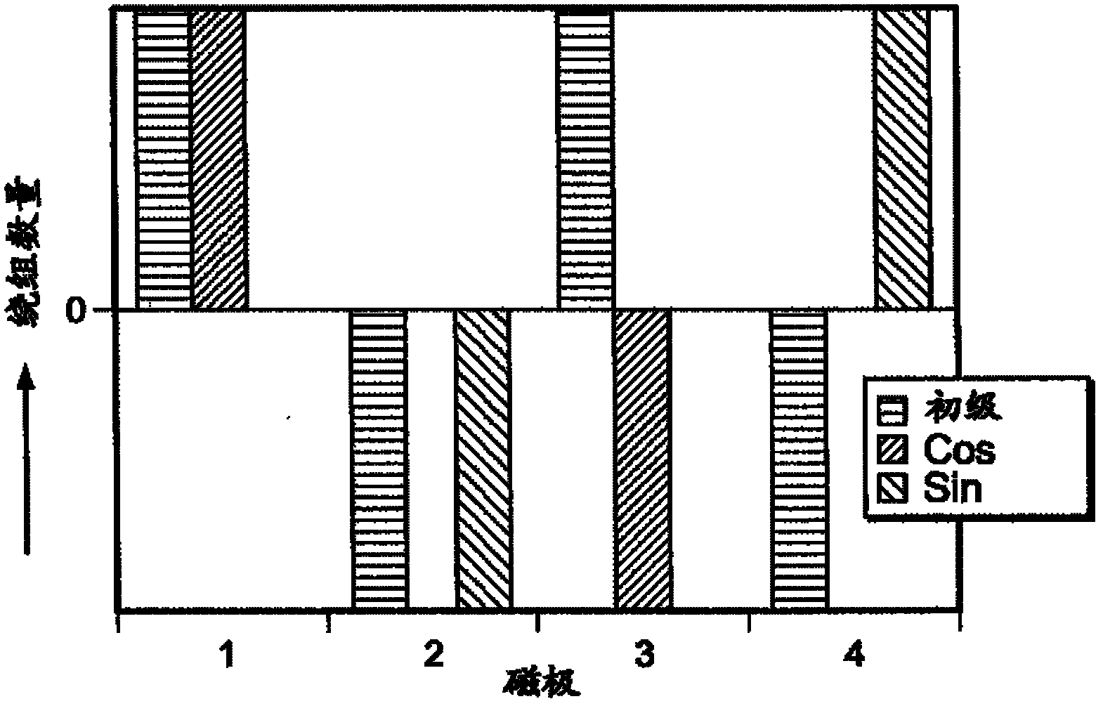
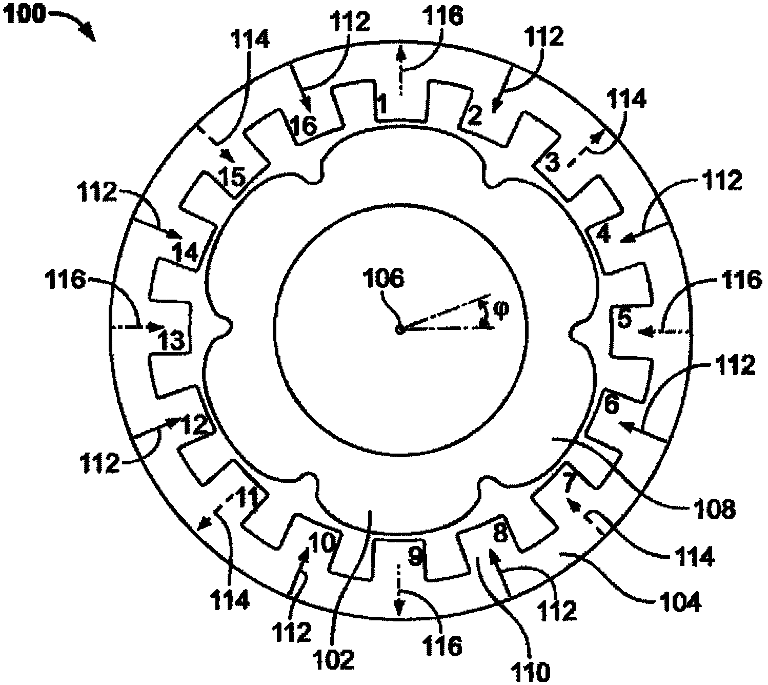
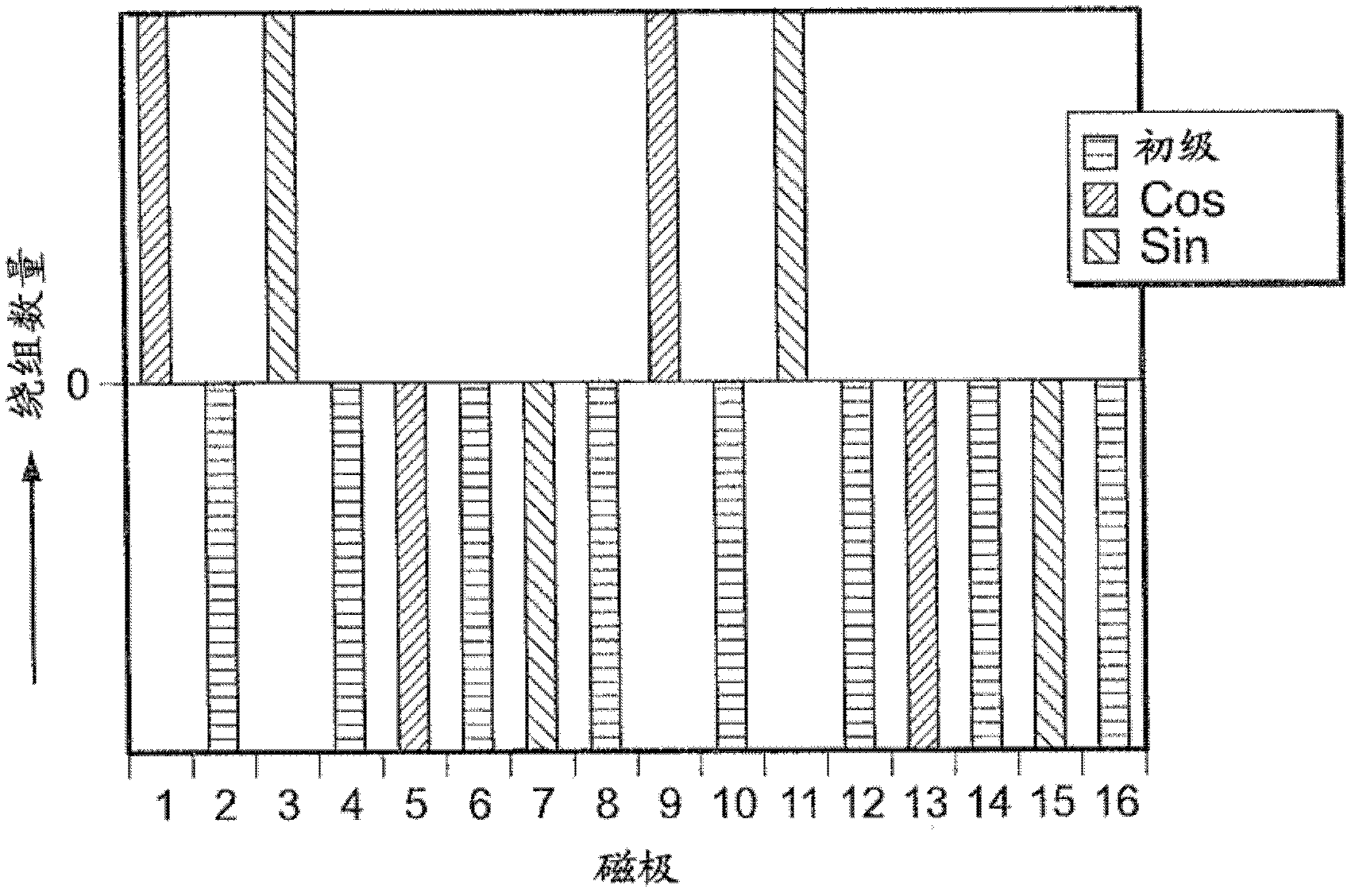
[0039] figure 2 is a schematic cross-sectional view through the six-speed resolver 100 according to the first embodiment of the present invention. In this case, a soft magnetic rotor 102 is mounted within a stator 104 to be rotatable about a rotational axis 106 . The rotor in the embodiment shown in this figure has six lugs 108 which, during rotation about the axis 106 , create a variable air gap between the teeth 110 of the stator 104 and the rotor 102 . The six-speed resolver configuration as shown in this figure provides a total of sixteen teeth 110, which are figure 2 Numbered sequentially in a clockwise direction. The magnetic flux occurring on the teeth 110 is marked by arrows. According to the invention, the even numbered teeth, which may also be called poles, in this case carry primary windings wound such that their magnetic flux 112 is directed towards the axis of rotation 106 when the exciting primary current is positive. The direction is directed inward. The magn...


PUM


Abstract

The present invention relates to a reluctance resolver (100) with an at least partially soft magnetic stator (104) and an at least partially soft magnetic rotor (102) which oppose each other by forming an air gap. The magnetic resistance in the air gap changes periodically on account of a configuration of the rotor that varies over the circumference. The angle sensor has a magnetic flux transmitter which is arranged on the stator and generates a predefined magnetic flux distribution in the air gap via at least one pair of poles. Furthermore, a magnetic flux receiver, which measures the intensity of the magnetic field via at least two pairs of signal poles arranged offset from one another at an angle, is arranged on the stator, wherein an angle value for a position of the rotor in relation to the stator can be derived from the two receiver signals. According to the invention, the stator (104) has distributed over the circumference a large number of teeth (110) which are separated from one another by grooves, and the magnetic flux transmitter comprises at least two primary windings which are arranged in such a way that at least one of the teeth carries no primary windings.

Description

technical field [0001] The invention relates to an electromagnetic angle sensor, in particular a reluctance resolver, having a rotationally symmetrical at least partially magnetically soft stator and a rotationally symmetrical at least partially magnetically soft rotor, said rotor and stator being opposed to each other by forming an air gap . The reluctance in the air gap varies periodically due to the circumferentially varying configuration of the rotor. The angle sensor has a magnetic flux transmitter which is arranged on the stator and generates a predetermined magnetic flux distribution in the air gap via at least one pair of magnetic poles. Furthermore, a flux receiver, which measures the magnetic field strength via at least two pairs of signal poles arranged angularly offset from each other, is arranged on the stator, wherein an angular value of the position of the rotor relative to the stator can be obtained from the two receiver signals. Background technique [000...

Claims


Application Information

Patent Timeline
IPC IPC(8): G01D5/20
CPCG01B7/30G01B7/14G01D5/2046H01F5/00G01D5/145
Inventor T.奥克特J.范考温伯格J.沃斯特莱特
Owner TYCO ELECTRONICS BELGIUM EC
Why Eureka
Try Eureka