
High-viscosity rapid drying machine

A fast-drying, high-viscosity technology, used in dryers, drying solid materials, drying, etc., can solve the problems of inability to dry high-viscosity and high-humidity materials, continuous production, and low dryer efficiency, and increase drying contact. Area, sufficient contact with hot air, and the effect of improving thermal efficiency

Active Publication Date: 2013-11-13
HE BEI NEWTHREETALENT ENVIRONMENTAL TECH CO LTD
View PDF4 Cites 0 Cited by
  • Summary
  • Abstract
  • Description
  • Claims
  • Application Information

AI Technical Summary

Problems solved by technology

[0006] To sum up, it can be seen that many high-moisture and high-viscosity materials are often dried in a drying room at present. Drum dryers can only dry high-viscosity and high-humidity materials that have a better cloth film and are easy to clean after drying. If the final moisture content of the dried product is relatively low At this time, the efficiency of this kind of dryer is extremely low or it is not suitable for use; the stirring dryer can only dry medium-viscosity and high-humidity materials, and it is powerless for materials like "rubber bands" that appear during drying. The quality is poor; the fluidized bed can only be used in several typical high-viscosity products, such as amide, potassium acrylate, etc., and it cannot dry nearly liquid high-viscosity and high-humidity materials at all
The existing drying equipment still has the disadvantages of bulky size, uneven moisture content of dried products, poor product quality, incapable of continuous production but intermittent production, and high labor intensity of workers.

Method used


Image

  • High-viscosity rapid drying machine
  • High-viscosity rapid drying machine
  • High-viscosity rapid drying machine

Examples


Embodiment 1

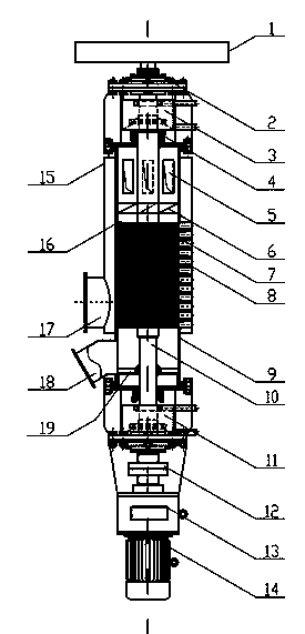
[0033] figure 1 and Figure 4 -6 shows a high-viscosity quick dryer, including the main body of the vertical dryer. The main body of the vertical dryer includes an inner shell 9, and the center of the inner shell 9 is provided with a main shaft 10. The main shaft 10 is supported and fixed by the bearing group 2 outside the two ends of the inner shell 9, and the two ends of the inner shell 9 are also equipped with shaft seals. 4.

[0034] There is also an upper cooling water tank 3 between the shaft seal 4 and the bearing group 2 at one end, and the inner shell 9 in this section is covered with an insulation layer; the lower cooling water tank 11 is also provided between the shaft seal 4 and the bearing group 2 at the other end. The inner shell 9 of the section is covered with an insulation layer.

[0035] The drive motor 14 is also connected to the input end of the main shaft 10 after passing through the gear box 13 and the shaft coupling 12 .

[0036] The middle part of t...

Embodiment 2

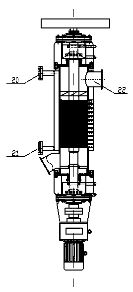
[0047] figure 2 and Figure 4 -6 is a high-viscosity rapid dryer, which is a medium-temperature (100-250°C) dryer, suitable for high-viscosity and high-humidity materials such as amides with a molecular weight of 1 million to 2 million, sprinkled grains, and pomace. The drying medium is Hot liquid such as hot oil, hot water, can also be hot water vapor.

[0048] The difference between this embodiment and embodiment 1 only lies in:

[0049] (1) There is no inner air inlet in this embodiment;

[0050] (2) The air inlet 17 in Embodiment 1 is replaced by the heat transfer oil inlet, hot water inlet or condensed water outlet 21 in this embodiment;

[0051] (3) The upper end of the jacket 15 and the upper part of the turbofan 6 are provided with a heat transfer oil outlet, a hot water outlet or a steam inlet 20 communicating with the inner cavity of the jacket 15 .

[0052] (4) The upper end of the jacket 15 and the upper part of the turbofan 6 are provided with an exhaust gas ...

Embodiment 3

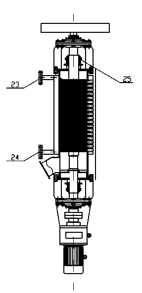
[0055] image 3 , Figure 5 , Image 6 Shown is a high-viscosity quick dryer, which is a low-temperature vacuum type (50-100°C) dryer, suitable for treating amides with a molecular weight of more than 2 million (it will glue if it exceeds 700°C), municipal sludge, etc., which require no odor For high-viscosity and high-humidity materials, the drying medium is hot liquid such as hot water, or hot water vapor.

[0056] The difference between this embodiment and embodiment 2 only lies in:

[0057] (1) There is no upper cooling water tank 3 and lower cooling water tank 11 in this embodiment;

[0058] (2) The shaft seal 4 in embodiment 2 is replaced by the mechanical seal 25 in this embodiment;

[0059] (3) There is no waste gas or secondary steam inlet 22 in this embodiment;

[0060] (4) The heat transfer oil inlet, hot water inlet or condensed water outlet 21 in Embodiment 2 are replaced by hot water inlet or condensed water outlet 24 in this embodiment;

[0061] (5) The he...


PUM


Abstract

The invention discloses a high-viscosity rapid drying machine which comprises a vertical dryer main body provided with an inner shell and a main shaft. The high-viscosity rapid drying machine is characterized in that a string of geared flywheels are fixedly arranged on the main shaft at intervals along an axial direction; and turbine fans are arranged at intervals above the geared flywheels and used for moderate-temperature drying and high-temperature drying. According to the high-viscosity rapid drying machine, the drying evaporating area is increased through action between the mechanical geared flywheels arranged on the main shaft and a material; and the high-efficiency heat transfer and mass transfer purpose can be realized through vortex generated by the geared flywheel and turbine fan structure. The high-viscosity rapid drying machine has the advantages of high safety performance, low energy consumption, no need of backmixing, extremely high equipment efficiency, compact structure, low operating cost, less system equipment, small occupied area, less investment, continuous operating effect and rapidness in drying, is applicable to various materials with different viscosity and humidity, is suitable for drying various high-viscosity high-humidity materials, can be widely applied to the fields such as printing and dyeing, chemical industry, medicines, municipal administration, cultivation, petrochemical industry and the like and can be used for drying thermosensitive materials.

Description

technical field [0001] The invention relates to a drying equipment for special materials, in particular to a fast drying machine for high-viscosity materials. Background technique [0002] Drying high-moisture and high-viscosity materials has always been a difficult point in the drying industry. These materials are non-Newtonian liquid materials, some are softened solids, some are semi-fluid, and basically cannot be transported by positive displacement pumps; some materials are slurry Thin or paste-like, high humidity makes it difficult to extrude and granulate (it cannot be granulated, and it sticks together after extrusion), and it is difficult to form. [0003] The commonly used drying room drying method has low efficiency; mixing paddle drying has sticky materials around the axis, the bond is firm and difficult to clean, and when the material is dried to a critical point, the drying efficiency is lower and the paddles are easy to entangle, making the equipment lose its o...

Claims


Application Information

Patent Timeline
Patent Type & Authority Patents(China)
IPC IPC(8): B01D1/24B01D1/00F26B17/00F26B25/02C02F11/12
CPCY02P20/10
Inventor 彭光辉韩宏亮张彦博
Owner HE BEI NEWTHREETALENT ENVIRONMENTAL TECH CO LTD
Learn More