
Device and method for assisting in injecting grinding liquid in grinding wheel airflow field

An airflow field and grinding fluid technology, applied in the field of grinding fluid supply, can solve the problems of complex structure, high cost, and easy vibration of the grinding wheel in the liquid supply system

Active Publication Date: 2012-05-02
QINGDAO TECHNOLOGICAL UNIVERSITY
View PDF5 Cites 3 Cited by
  • Summary
  • Abstract
  • Description
  • Claims
  • Application Information

AI Technical Summary

Problems solved by technology

Since the high-pressure jet can easily break through the barrier of the formed vapor film and ensure the continuous contact between the grinding fluid and the surface of the workpiece, it is possible to break through the barrier of film boiling and reduce the temperature of the grinding arc zone. This cooling fluid injection method is not suitable. Affected by the gas barrier of the grinding wheel, the heat transfer efficiency is high, but the disadvantage is that the grinding wheel is prone to vibration during operation, resulting in reduced precision and surface quality of the workpiece, and the liquid supply system has a complex structure and high cost

Method used


Image

  • Device and method for assisting in injecting grinding liquid in grinding wheel airflow field
  • Device and method for assisting in injecting grinding liquid in grinding wheel airflow field
  • Device and method for assisting in injecting grinding liquid in grinding wheel airflow field

Examples


Embodiment Construction

[0064] The present invention will be further described below in conjunction with the accompanying drawings and embodiments.

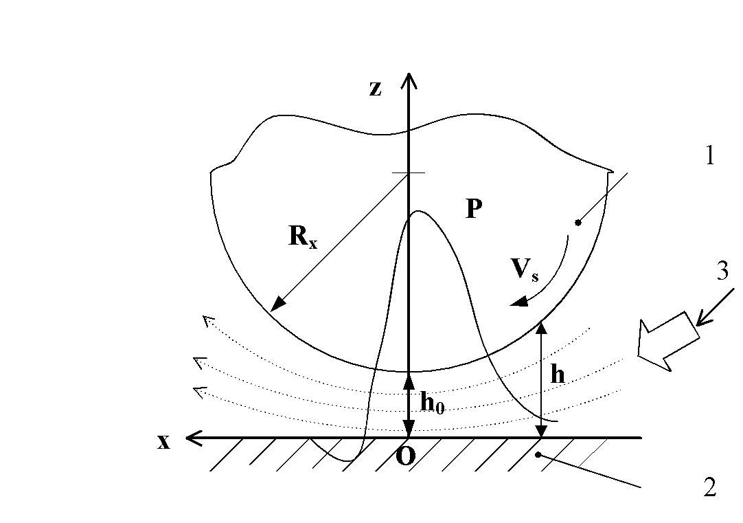
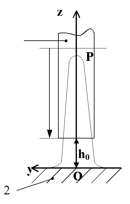
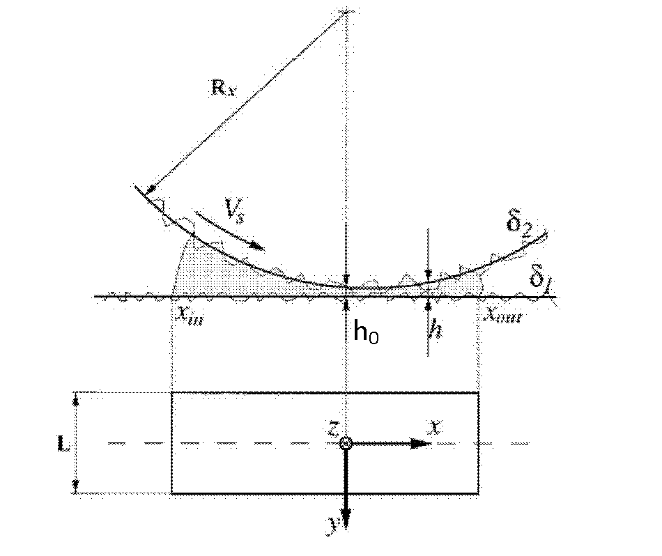
[0065] Figure 1a Among them, a method for assisting the injection of grinding fluid by the airflow field of the grinding wheel of the present invention, the position of the nozzle for supplying the grinding fluid is set above the return flow of the airflow field in the wedge-shaped grinding area, and the position is tangent to the circumference of the grinding wheel; The speed of the grinding fluid is equal to the peripheral speed of the grinding wheel. With the help of the speed of the grinding wheel and the energy obtained from the rapid increase of the pressure and velocity of the airflow field in the wedge grinding area, the auxiliary grinding fluid is injected into the cutting area.

[0066] The exit position of the nozzle is 0.5-1mm away from the surface of the grinding wheel 1; the distance between the exit of the nozzle and the workpiece is 60-...


PUM


Abstract

The invention relates to a device and method for assisting in injecting grinding liquid in the grinding wheel airflow field. A spraying nozzle for supplying grinding liquid is arranged on return flow in the airflow field in a wedge-shaped grinding zone and is tangent to the circumference of a grinding wheel; the grinding liquid spraying speed of the spraying nozzle equals the circumferential speed of the grinding wheel; and the energy obtained due to the rapid increase of the speed of the grinding wheel and the pressure and speed of the airflow field in the wedge-shaped grinding zone is used for assisting in the injection of the grinding liquid into the wedge-shaped grinding zone. In the invention, the influence of the air barrier of the grinding wheel can not be generated, and the idle work energy of a grinding liquid supplying system is saved. The spraying nozzle for supplying the grinding liquids tangent to the circumference of the grinding wheel, and the grinding liquid spraying speed of the spraying nozzle equals the circumferential speed of the grinding wheel, thus the grinding liquid can be more effectively injected into the wedge-shaped grinding zone under the drag of the grinding wheel. Because the dynamic pressure and speed of the grinding wheel airflow field increase greatly in the wedge-shaped grinding zone, more power and energy can be obtained for the grinding liquid in the wedge-shaped grinding zone. Because the negative pressure is formed behind the minimum clearance of wedge-shaped grinding zone, the flow rate of the grinding liquid flowing through the grinding wheel and a workpiece interface is increased.

Description

technical field [0001] The invention belongs to a method for supplying grinding fluid in mechanical processing, namely a method and a device for assisting injection of grinding fluid by a grinding wheel air field. Background technique [0002] In grinding, the energy consumed per unit volume of material is much greater than other cutting methods, and a large amount of heat is generated in the grinding area, which is dissipated on chips, tools and workpieces. The thermal effect of grinding has a great influence on the surface quality and performance of the workpiece. Especially when the temperature exceeds a certain critical value on the grinding wheel / workpiece interface, it will cause surface thermal damage (oxidation, burns, residual tensile stress and cracks on the surface), which will result in reduced wear resistance of the parts. The anti-fatigue performance is deteriorated, thereby reducing the service life of the parts and the reliability of the workpiece. In addit...

Claims


Application Information

Patent Timeline
Patent Type & Authority Applications(China)
IPC IPC(8): B24B57/02B24B55/02
Inventor 侯亚丽李长河
Owner QINGDAO TECHNOLOGICAL UNIVERSITY
Learn More