
Fusing and mixing device

A technology of fusion mixing and guide tube, which is applied in the direction of fertilization device, fertilizer mixture, application, etc., can solve the problems of reduced diameter of stirring blade, reduced stirring intensity, and reduced tangential speed, etc., to reduce heat loss, strengthen mixing, and save energy. The effect of cost

Active Publication Date: 2012-05-02
拉多美科技集团股份有限公司
View PDF7 Cites 4 Cited by
  • Summary
  • Abstract
  • Description
  • Claims
  • Application Information

AI Technical Summary

Problems solved by technology

The stirring paddle used is an ordinary paddle blade, and the viscosity range of the applicable medium is less than 2000mPa.s, while the viscosity of the compound fertilizer melt is mostly 5000mPa.s or higher, and its stirring effect is poor.
In addition, because the device is equipped with an inner coil, the diameter of the stirring blade is reduced, and the tangential velocity of the stirring blade end is reduced at the same speed, and the stirring intensity is reduced.
At the same time, due to the influence of the inner coil on the mixing, the loading capacity is also reduced. Under the same effective volume, a larger pot is required.

Method used


Image

  • Fusing and mixing device
  • Fusing and mixing device
  • Fusing and mixing device

Examples


Embodiment 1

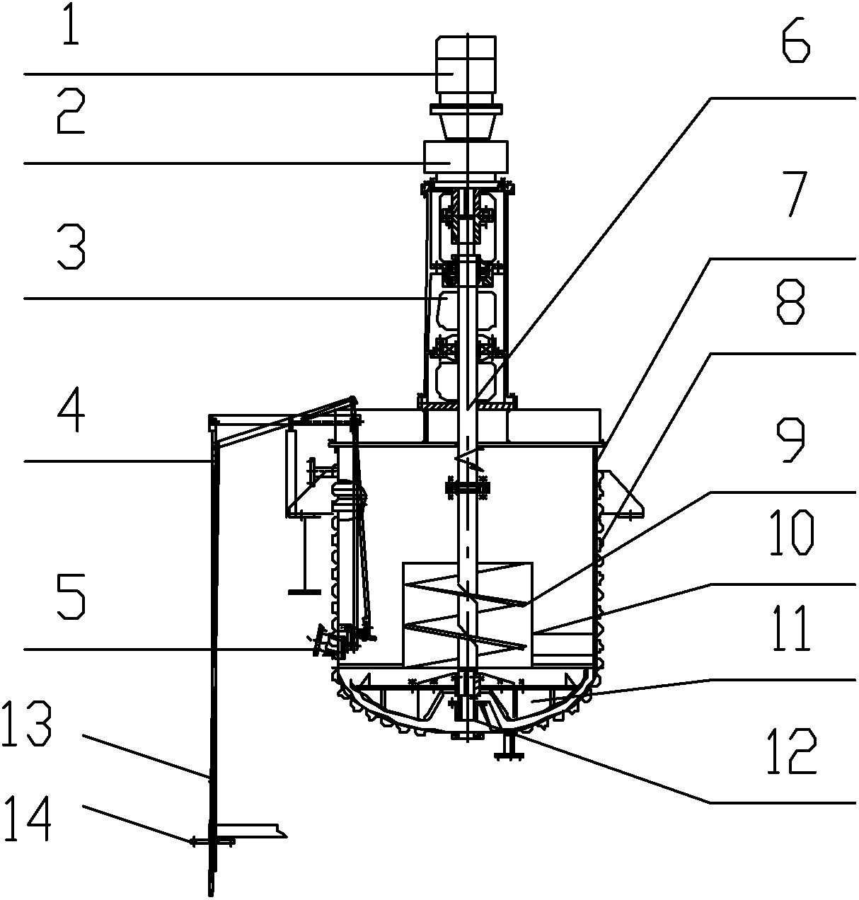
[0033] A melting and mixing device includes a transmission device, a pot cover, a discharge valve assembly, a discharge pipe, a stirring shaft, a pot body, an external heat preservation device, a stirring device and a shaft sleeve.

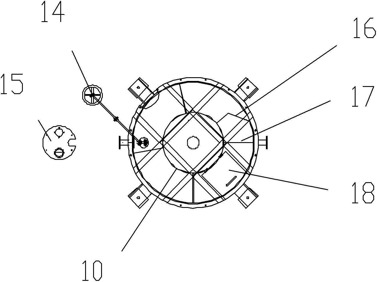
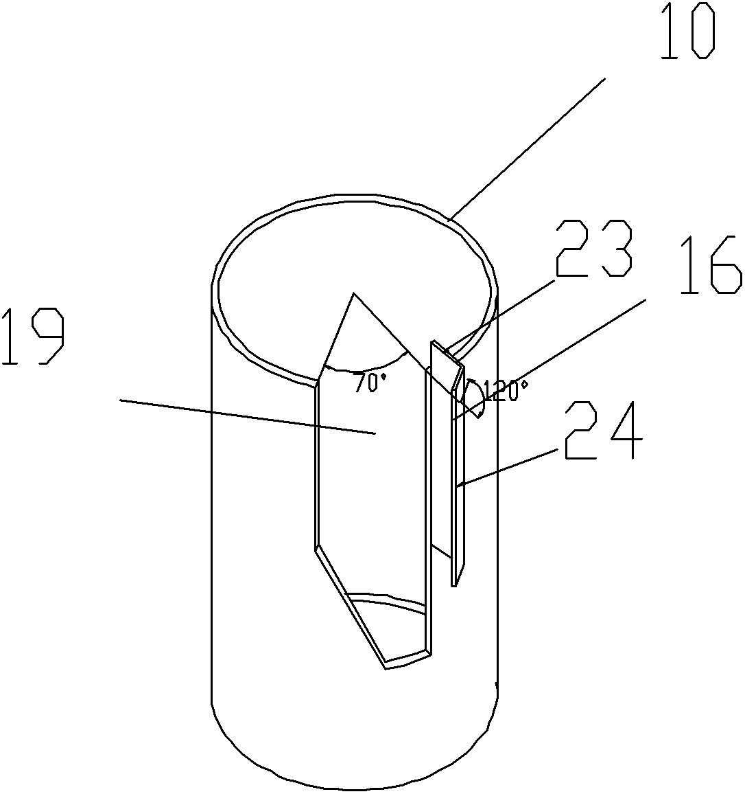
[0034] The stirring device includes a screw stirring paddle and a guide tube, and the guide tube is a hollow cylindrical body which is sheathed outside the screw stirring paddle and has upper and lower openings.

[0035] The rotating device includes a transmission motor 1 , a reducer 2 and a reducer support 3 .

[0036]An explosion-proof transmission motor 1 is mounted on a reducer 2 . The helical gear reducer 2 is installed on the reducer support 3, and the double fulcrum type reducer support 3 is fixed on two channel steels on the pot cover surface. The pot body 7 is made of thick 12mm304 stainless steel, and the bottom of the pot uses an elliptical head. The diameter of the pot body is 1.8m, and the height of the pot body is 1.8m. Open a weld...

Embodiment 2

[0040] A melting and mixing device includes a transmission device, a pot cover, a discharge valve assembly, a discharge pipe, a stirring shaft, a pot body, an external heat preservation device, a stirring device and a shaft sleeve.

[0041] The stirring device includes a screw stirring paddle and a guide tube, and the guide tube is a hollow cylindrical body which is sheathed outside the screw stirring paddle and has upper and lower openings.

[0042] A notch extending downward from the upper edge of the draft tube is provided on the tube wall of the draft tube, and the gap is located at the angle between the two end points of the upper edge of the draft tube and the center point of the upper edge of the draft tube. 60°. Other structures are the same as in Embodiment 1.

[0043] Through the implementation of the invention, heat loss can be reduced by 8%-13%, electric energy can be saved by 7%-16%, construction cost can be saved by 15%-30%, and production capacity can be increa...

Embodiment 3

[0045] A melting and mixing device includes a transmission device, a pot cover, a discharge valve assembly, a discharge pipe, a stirring shaft, a pot body, an external heat preservation device, a stirring device and a shaft sleeve.

[0046] The stirring device includes a screw stirring paddle and a guide tube, and the guide tube is a hollow cylindrical body which is sheathed outside the screw stirring paddle and has upper and lower openings.

[0047] A notch extending downward from the upper edge of the draft tube is provided on the tube wall of the draft tube, and the gap is located at the angle between the two end points of the upper edge of the draft tube and the center point of the upper edge of the draft tube. 80°. Other structures are the same as in Embodiment 1.

[0048] Through the implementation of the invention, heat loss can be reduced by 7%-12%, electric energy can be saved by 8%-18%, construction cost can be saved by 15%-30%, and production capacity can be increa...


PUM


Abstract

The invention discloses a fusing and mixing device for producing a compound fertilizer by performing tower granulation. The fusing and mixing device comprises a transmission device, a pot cover, a discharging valve assembly, a discharging pipe, a stirring shaft, a pot body, an outer heat insulating device, a stirring device and a shaft sleeve, wherein the stirring device comprises a spiral stirring blade and a diversion cylinder; the diversion cylinder is a hollow cylindrical body which is sleeved outside the spiral stirring blade and is opened on the top and at the bottom; the cylinder wall of the diversion cylinder is provided with a gap extending downwards from the upper edge of the diversion cylinder; included angles between lines of the two end points of the gap on the upper edge of the diversion cylinder and the central point of the upper edge of the diversion cylinder are 60-80 degrees; the gap is three fourth to four fifth of the height of the diversion cylinder; and a baffle plate is arranged between one side of the gap along the downstream direction of the slurry flowing direction and a pot wall. In the fusing and mixing device, a stirring device with small heat loss is adopted, so that the use of an inner coil is reduced, the manufacturing cost is saved, the energy is saved, and the stirring efficiency is increased simultaneously.

Description

technical field [0001] The invention relates to production equipment for agricultural compound fertilizers, in particular to a melting and mixing device for producing compound fertilizers by tower granulation. Background technique [0002] In the compound fertilizer tower granulation process, the powdery solid material is heated and mixed at high temperature to form a composite molten slurry with a certain viscosity and fluidity. Droplets naturally fall downward from the top of the prilling tower. During the falling process, the liquid droplets contact the cold air in the prilling tower, cooling and shrinking into spherical granule products. [0003] The molten slurry must reach the higher temperature required for granulation in order to meet the requirements of granulation. The existing mixing device for producing compound fertilizer pulp from tower melt, such as Chinese patents 200510060037.4 and 200510096470.3, mainly adopts the internal mixing device. Coil heaters to ma...

Claims


Application Information

Patent Timeline
Patent Type & Authority Applications(China)
IPC IPC(8): C05G1/00
Inventor 王晓春罗冬贵
Owner 拉多美科技集团股份有限公司
Learn More