
High temperature sintering kiln

A high-temperature sintering and kiln technology, applied in the field of kiln equipment, can solve the problems of production efficiency impact, easy damage of silicon molybdenum rods, large energy loss, etc., and achieve the effect of saving energy in the production process and avoiding large energy consumption

Inactive Publication Date: 2012-05-02
湖南阳东微波科技有限公司
View PDF5 Cites 15 Cited by
  • Summary
  • Abstract
  • Description
  • Claims
  • Application Information

AI Technical Summary

Problems solved by technology

[0003] In the prior art, there are mainly the following two production methods for industrial production of vanadium-nitrogen alloys: the first is to use conventional continuous high-temperature sintering kilns to produce vanadium-nitrogen alloys. Although this method can be continuously produced in large quantities and the product The quality is relatively stable, but it uses materials such as silicon-molybdenum rods to heat the production materials in a thermal radiation manner, which takes a long time to heat and consumes a lot of energy. Also, due to the high temperature of the silicon-molybdenum rod itself (up to 1000-1800°C), the silicon-molybdenum rod itself The rod is easily damaged, which has a great impact on production efficiency; the second is the production method of the vanadium-nitrogen alloy described in the patent application number 200410023094.0, which uses industrial microwave ovens to heat the vanadium-nitrogen alloy raw materials for intermittent production. Microwave heating is used to heat the production materials, which reduces energy consumption, but it cannot achieve continuous production, which makes the output of vanadium nitrogen alloys low, and cannot meet production needs under certain circumstances

Method used


Image

  • High temperature sintering kiln
  • High temperature sintering kiln
  • High temperature sintering kiln

Examples


Embodiment Construction

[0037] The invention provides a high-temperature sintering kiln, which realizes the purpose of energy-saving and high-efficiency continuous production of vanadium-nitrogen alloys, and greatly improves production efficiency.

[0038] The following will clearly and completely describe the technical solutions in the embodiments of the present invention with reference to the accompanying drawings in the embodiments of the present invention. Obviously, the described embodiments are only some, not all, embodiments of the present invention. Based on the embodiments of the present invention, all other embodiments obtained by persons of ordinary skill in the art without making creative efforts belong to the protection scope of the present invention.

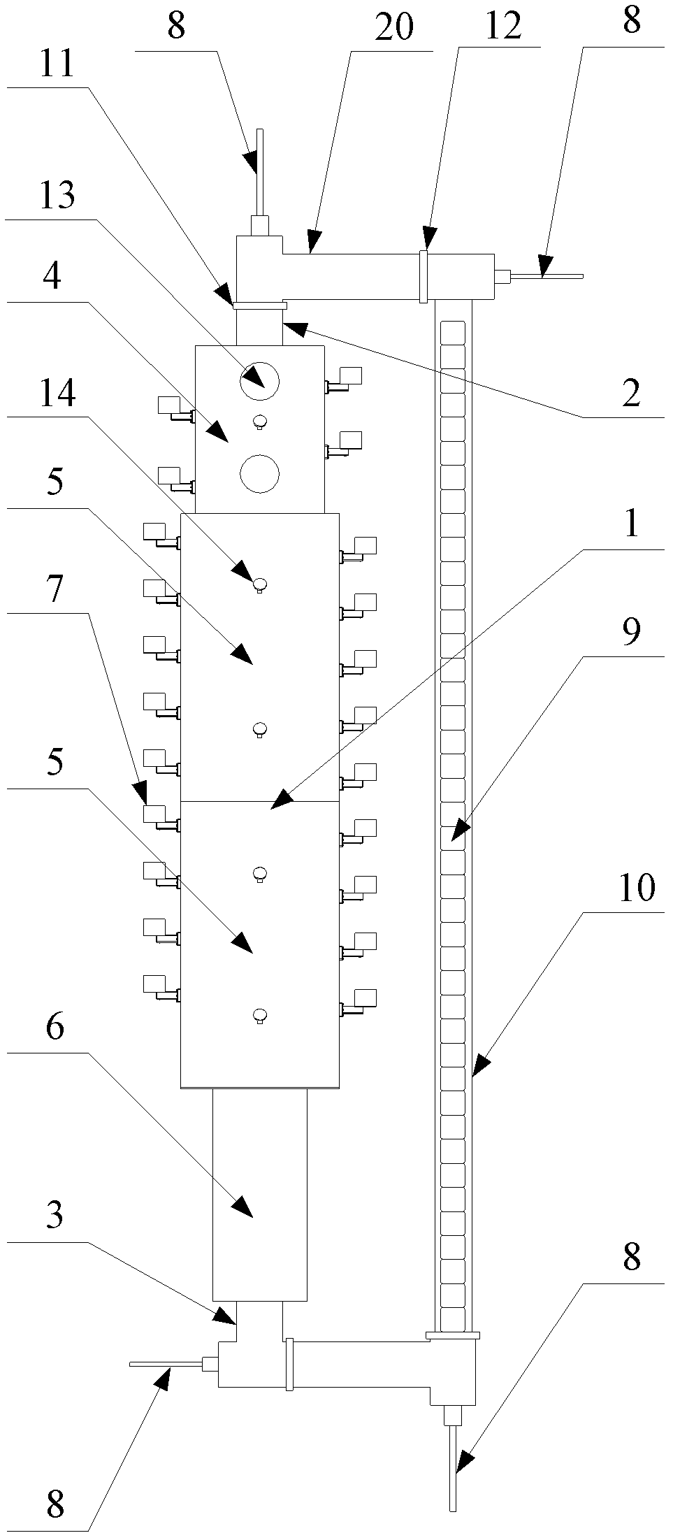
[0039] Please refer to the attached figure 1 , figure 1 The top view of the high-temperature sintering kiln provided for the embodiment of the present invention.

[0040] The high-temperature sintering kiln provided by the embodiment of...


PUM


Abstract

The invention provides a high temperature sintering kiln, which comprises a kiln body (1), a plurality of microwave heating devices (7) arranged on the kiln body (1) and transmitting microwave to the inside of the kiln body (1), a closed type polygon track (10), a push rod (8) and a controller. The kiln body (1) is provided with a temperature rising section (4) communicated with a feeding port (2) of the kiln body (1), a high temperature section (5) communicated with the temperature rising section (4) and a cooling section (6) communicated with the high temperature section (5) and a discharging port (3) of the kiln body (1). One side of the closed type polygon track (10) penetrates through the kiln body (1), and the closed type polygon track is provided with the closed type polygon track (10) of a push plate (9) for containing vanadium nitrogen alloy materials (19). The push rod (8) is arranged at the turning position of the closed type polygon track (10) and capable of pushing the push plate (9) to move on the closed type polygon track (10). The controller controls the push rod (8) and the microwave heating device (7) to work. The high temperature sintering kiln enables the production process to be more energy-saving and higher in efficiency while achieving continuous production.

Description

technical field [0001] The invention relates to the technical field of kiln equipment, more specifically, to a high-temperature sintering kiln. Background technique [0002] According to the research of modern material science, when the steel contains a certain amount of vanadium element and a certain amount of nitrogen element, the performance of the steel can be greatly improved. Adding vanadium-nitrogen alloys to steel can promote the upgrading of steel products on the premise of the lowest cost. In practical applications, it has significant advantages such as improving the safety performance of buildings and products, reducing steel consumption, and saving costs. Therefore, vanadium-nitrogen alloys are used in Applications in the steel industry are becoming more and more common. [0003] In the prior art, there are mainly the following two production methods for industrial production of vanadium-nitrogen alloys: the first is to use conventional continuous high-temperatu...

Claims


Application Information

Patent Timeline
Patent Type & Authority Applications(China)
IPC IPC(8): F27B9/02F27B9/06F27B9/22F27B9/30F27B9/36F27B9/40
Inventor 刘伏初李蔚霞刘元月李启刚
Owner 湖南阳东微波科技有限公司
Learn More