Large-scale true triaxial experiment testing method and equipment

A test and true triaxial technology, applied in the direction of applying stable tension/pressure to test the strength of materials, measuring devices, instruments, etc., can solve problems such as unusable, easy to tear hydraulic bladders, and reduce vertical friction. Achieve the effect of convenient implementation, easy loading and overcoming frictional resistance

Inactive Publication Date: 2012-05-02
CHANGJIANG RIVER SCI RES INST CHANGJIANG WATER RESOURCES COMMISSION
View PDF5 Cites 40 Cited by
  • Summary
  • Abstract
  • Description
  • Claims
  • Application Information

AI Technical Summary

Problems solved by technology

[0005] The true triaxial instrument disclosed in the prior art, one is a true triaxial instrument with a three-way independent loading pressure chamber structure applied by Xi'an University of Technology (patent number: CN200710019066.5), and its test size is 75mm*75mm*150mm , small principal stress σ 3 and intermediate principal stress σ 2 Four hydraulic bladders are used for loading, and the corners are separated by rigid plates. The maximum loading capacity is only 1.0MPa, and the loading bladder is easy to blow out. Second, the deformation applied by Hohai University is not subject to lateral interference. The test size of the true triaxial instrument (patent application number: CN200810243975.1) is 120mm*120mm*60mm, which is also a small-sized true triaxial instrument, with a large principal stress σ 1 and intermediate principal stress σ 2 The directional loading method belongs to rigid loading, although in the middle principal stress σ 2 The direction increase

Method used


Image

  • Large-scale true triaxial experiment testing method and equipment
  • Large-scale true triaxial experiment testing method and equipment
  • Large-scale true triaxial experiment testing method and equipment

Examples


Embodiment Construction

[0024] The technical solutions in the present invention will be clearly and completely described below in conjunction with the accompanying drawings in the present invention.

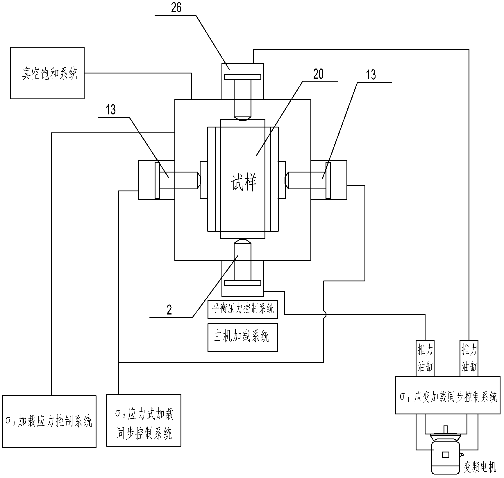
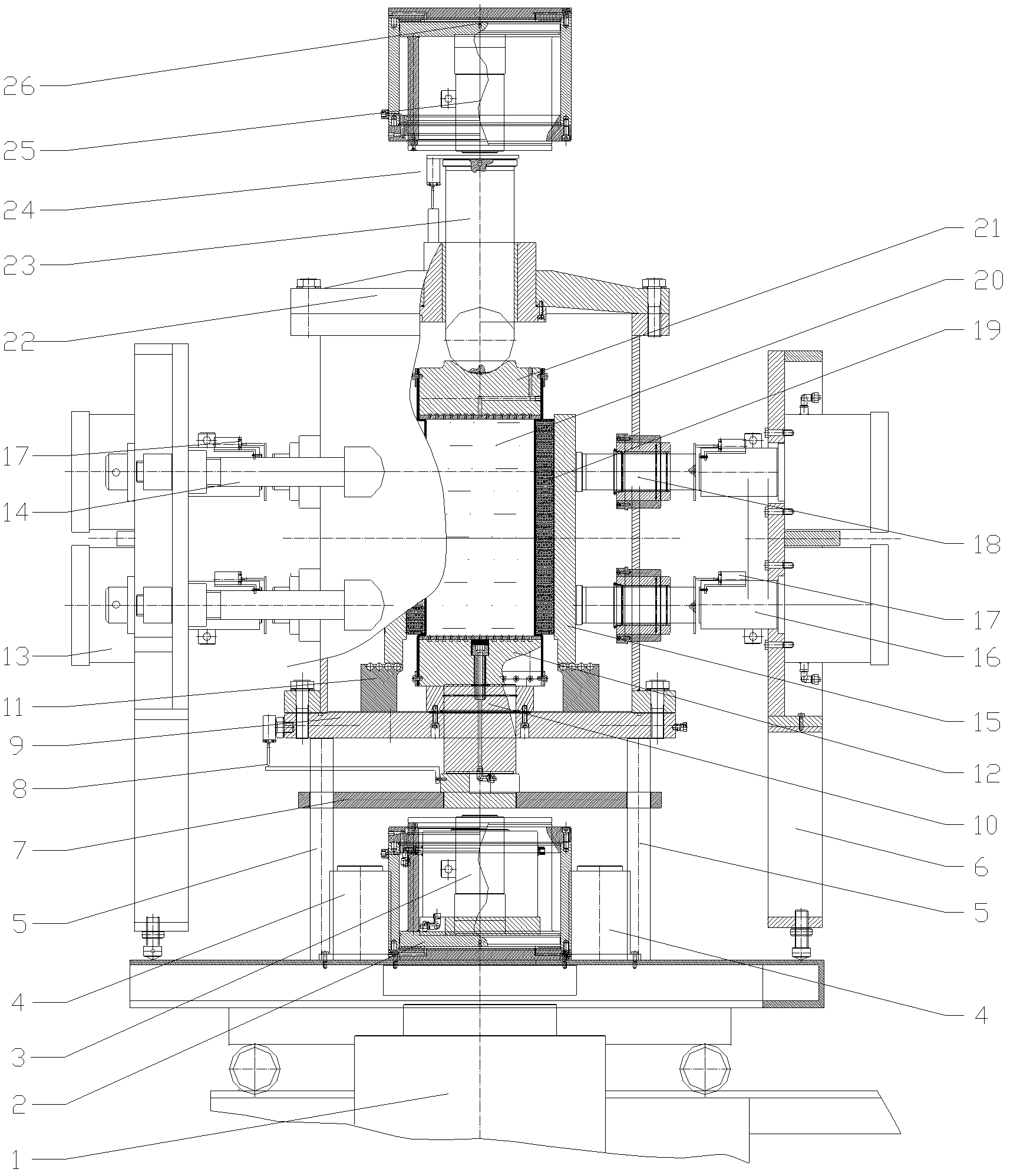
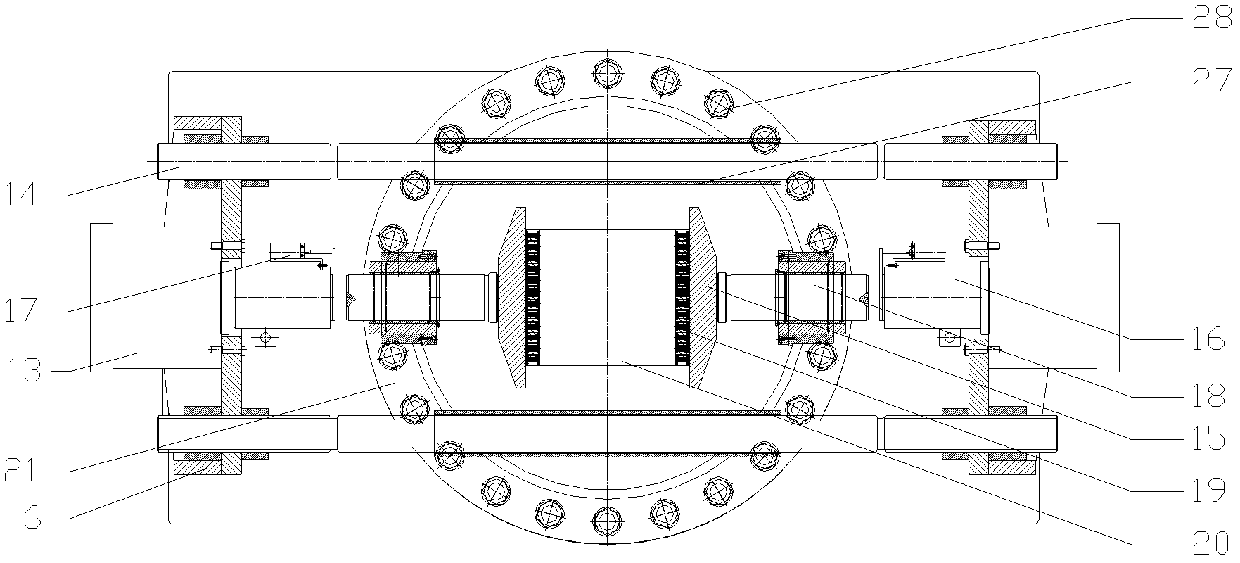
[0025] Please refer to Figure 1 ~ Figure 3 , the large true triaxial test equipment of the present invention includes σ 1 Strain loading synchronous control system, σ 2 Stress type loading synchronous control system, σ 3 Loading control system, balance pressure control system, vacuum saturation system, host loading system. Specifically, the pressure chamber 22 is tightly connected with the pressure chamber base 9 by bolts, and the first axial piston 10 is arranged on the pressure chamber base 9, and the first axial piston 10 is sealed and connected with the pressure chamber base 9 through a copper sealing sleeve. The upper part of the first axial piston 10 is welded with a sample base 12 with an area of ​​300×300 mm. The sample 20 is installed on the sample base 12. A compressible force transmission...


PUM


Abstract

The invention discloses large-scale true triaxial experiment testing equipment. A first axial piston is arranged on a pressure chamber base and connected with the pressure chamber base in a sealing mode by a sealing copper sleeve; the lower part of the first axial piston is connected with a balance disk; the upper part of the first axial piston is welded with a sample base; a sample is arranged on the sample base; a compressed force transferring plate and a lateral force transferring plate which can be deformed along with the sample are sequentially arranged on the two sides of the sample; the outside of the sample is sequentially connected with lateral pistons, sigma 2 load sensors and sigma 2 pressurizing oil cylinders; the sigma 2 pressurizing oil cylinders are fixed on lateral reaction force beams; four pull rods pass through a pressure chamber and are connected and fixed with the lateral reaction force beams at the two ends of each pull rod; and a second axial piston is arranged on the top of the pressure chamber and connected with the pressure chamber in a sealing mode by a sealing copper sleeve. The invention also provides a large-scale true triaxial experiment testing method. Pressure can be applied respectively to the sigma 1 direction, the sigma 2 direction and the sigma 3 direction of the sample by the invention, and the test technical requirements of the true triaxial experiment are met.

Description

technical field [0001] The invention relates to the technical field of geotechnical test methods and equipment, in particular to a large-scale true triaxial test test method and test equipment. Background technique [0002] Research on the deformation of earth-rockfill dam soil, the stress state at any point is three-phase, and there is a large principal stress σ 1 , small principal stress σ 3 and intermediate principal stress σ 2 . To carry out experimental research is to apply axial pressure to the soil (large principal stress σ 1 ), medium principal stress σ 2 , small principal stress σ 3 , to measure the axial pressure of the sample under different stress states (large principal stress σ 1 ) and intermediate principal stress σ 2 , Axial strain ε 1 and bulk strain ε v , to the failure of the sample, the relationship between the shear strength and the stress-strain of the sample is obtained. [0003] At present, an important method for the experimental study of t...

Claims


Application Information

Patent Timeline
IPC IPC(8): G01N3/12G01N3/02
Inventor 程展林左永振丁红顺张继勋
Owner CHANGJIANG RIVER SCI RES INST CHANGJIANG WATER RESOURCES COMMISSION
Why Eureka
Try Eureka