High-frequency fretting wear tester
A fretting wear and testing device technology, applied in the field of testing and wear testing, can solve problems such as cracks and their propagation trend hazards
- Summary
- Abstract
- Description
- Claims
- Application Information
AI Technical Summary
Problems solved by technology
Method used
Image

Examples
Embodiment approach 1
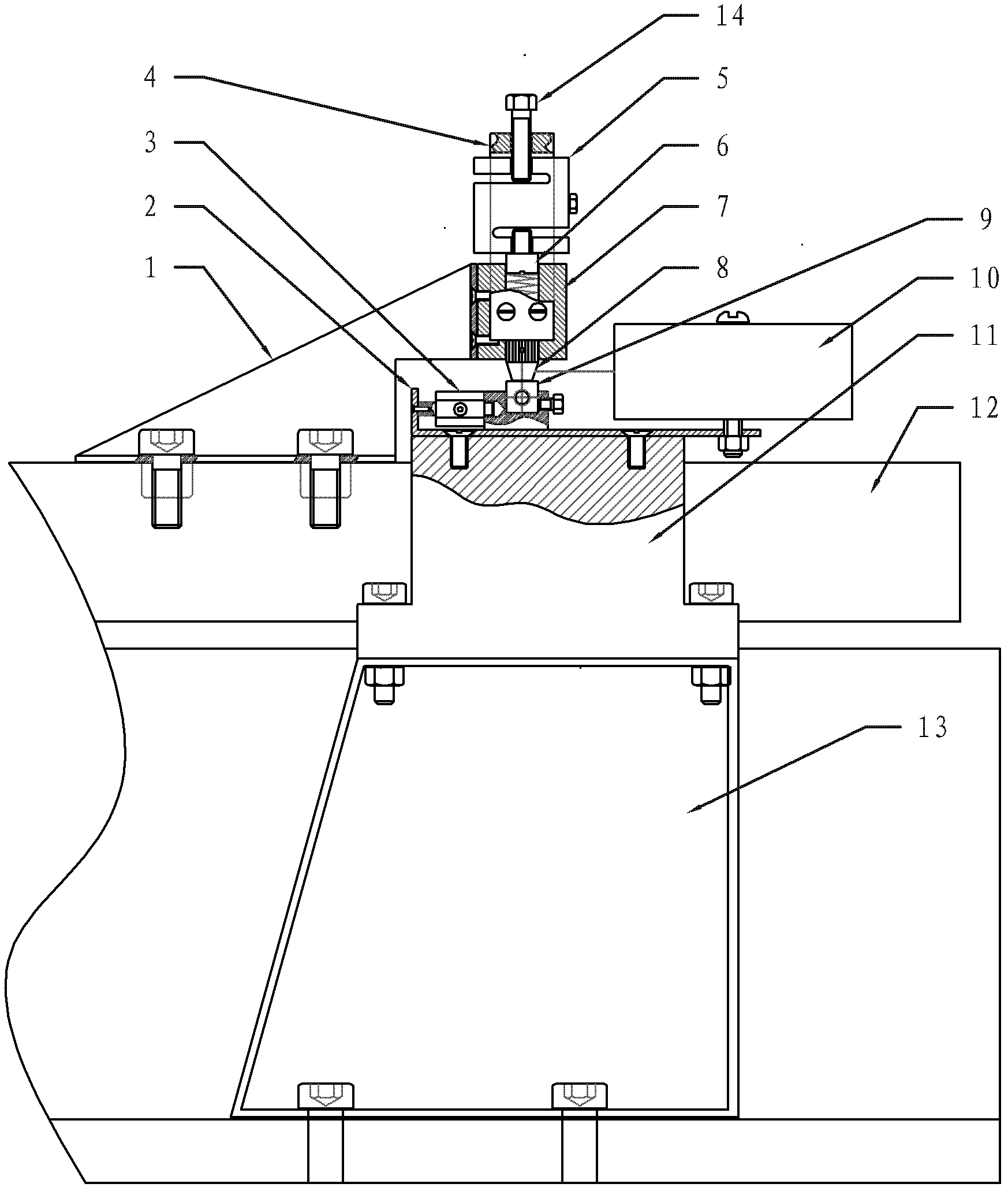
[0017] Embodiment 1: The high-frequency micro-motion wear test device described in this embodiment includes an electric vibration table, a micro-motion clamping mechanism, a wear mechanism, a laser displacement sensor 10, and a signal conditioning and acquisition circuit.
[0018] The electric vibration table is used to provide the micro-amplitude vibration required for testing fretting wear, and the micro-amplitude vibration refers to the sinusoidal vibration with an amplitude of micron level and a frequency of less than 2000Hz;
[0019] The vibrating table surface 12 of the electric vibrating table is fixedly connected with a micro-moving clamping mechanical structure, and the micro-moving clamping mechanical structure is used to clamp the first tested sample 8 to realize micro-amplitude vibration. The micro-moving clamping mechanical structure includes: a pre-pressure structure and a pressure sensor 5, the pre-pressure structure is used to provide a pre-compression force to ...
Embodiment approach 2
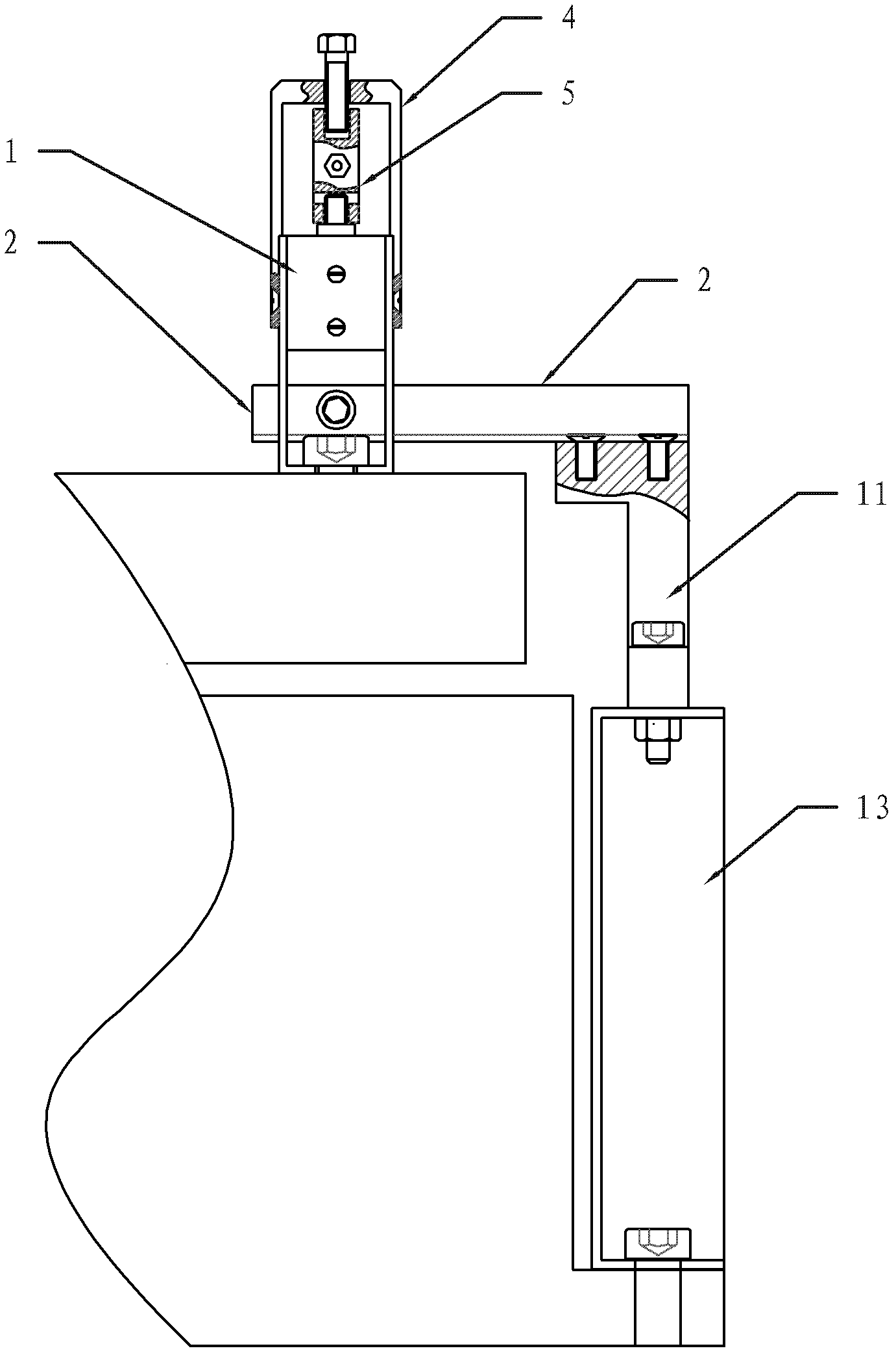
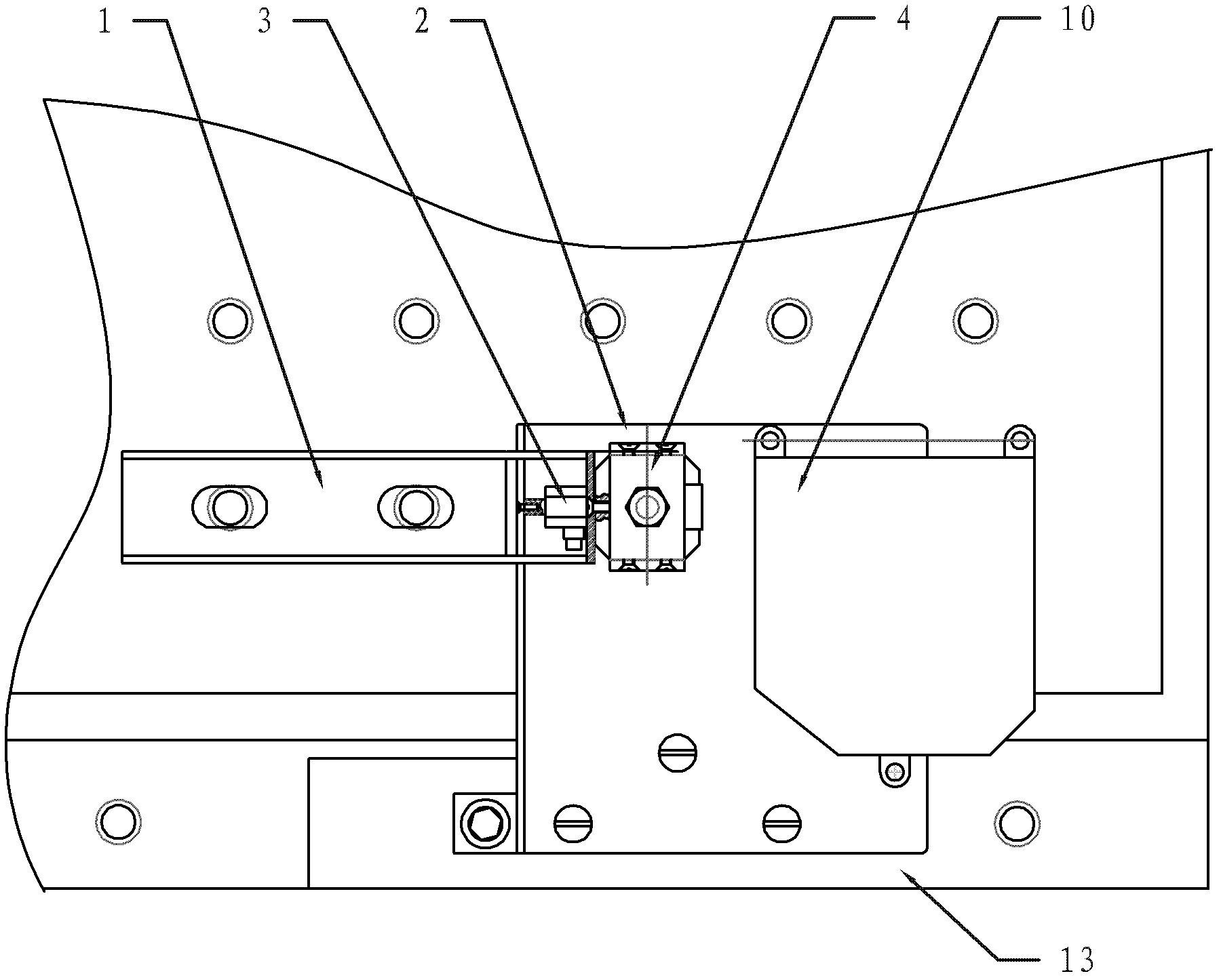
[0029] Embodiment 2: This embodiment is a further limitation of the micro-movement clamping mechanical structure in the high-frequency micro-motion wear test device described in the specific embodiment 1. The micro-motion clamping mechanical structure described in this It includes a support plate 1 and a sensor support frame 4, one end of the support plate 1 is fixedly connected with the vibration table surface 12 of the electric vibration table, and the other end of the support plate 1 is away from the vibration table surface 12 of the electric vibration table, and is connected with the pre-vibration table. The pressure structure is fixedly connected. The pre-pressure structure includes a sample slider 7, a sample clamping structure, a spring and a top wire 6. The other end of the support plate 1 is fixedly connected to the sample slider 7. The lower part of the sensor support frame 4 Fixed on the sample slider 7, the vertical through hole of the sample slider 7, the pressure ...
Embodiment approach 3
[0033] Embodiment 3: This embodiment is a further limitation of the wear mechanical structure in the high-frequency fretting wear test device described in the specific embodiment 1. The wear mechanical structure in this embodiment also includes a support angle piece 2, a sample holder Holder, corner piece support block 11 and wear mechanism support plate 13, the bottom of the wear mechanism support plate 13 is fixedly connected with the table body of the electric vibration table, and the top of the wear mechanism support plate 13 is connected with the corner piece support block 11. The bottom is fixedly connected, the top of the corner piece support block 11 is fixedly connected with the support corner piece 2, the installation plane of the support corner piece 2 is parallel to the vibration table surface 12 of the electric vibration table, and the support corner piece 2 is fixed with The laser displacement sensor 10 and the sample holder, one end of the sample holder is the sa...
PUM
 Abstract
Description
Claims
Application Information
 - R&D
- Intellectual Property
- Life Sciences
- Materials
- Tech Scout
- Unparalleled Data Quality
- Higher Quality Content
- 60% Fewer Hallucinations
Browse by: Latest US Patents, China's latest patents, Technical Efficacy Thesaurus, Application Domain, Technology Topic, Popular Technical Reports.
© 2025 PatSnap. All rights reserved.Legal|Privacy policy|Modern Slavery Act Transparency Statement|Sitemap|About US| Contact US: help@patsnap.com