Improved method for measuring impulse grounding resistance of electric power system

A technology of impacting grounding resistance and impacting current, which is applied in the direction of grounding resistance measurement, etc., and can solve problems such as significant inductive effect, high frequency of lightning current, and single structure

Inactive Publication Date: 2012-05-02
国网安徽省电力有限公司巢湖市供电公司
View PDF2 Cites 23 Cited by
  • Summary
  • Abstract
  • Description
  • Claims
  • Application Information

AI Technical Summary

Problems solved by technology

[0009] Due to the large size and non-uniform structure of the actual grounding body in the power system, and the high frequency of the lightning current, the inductance

Method used

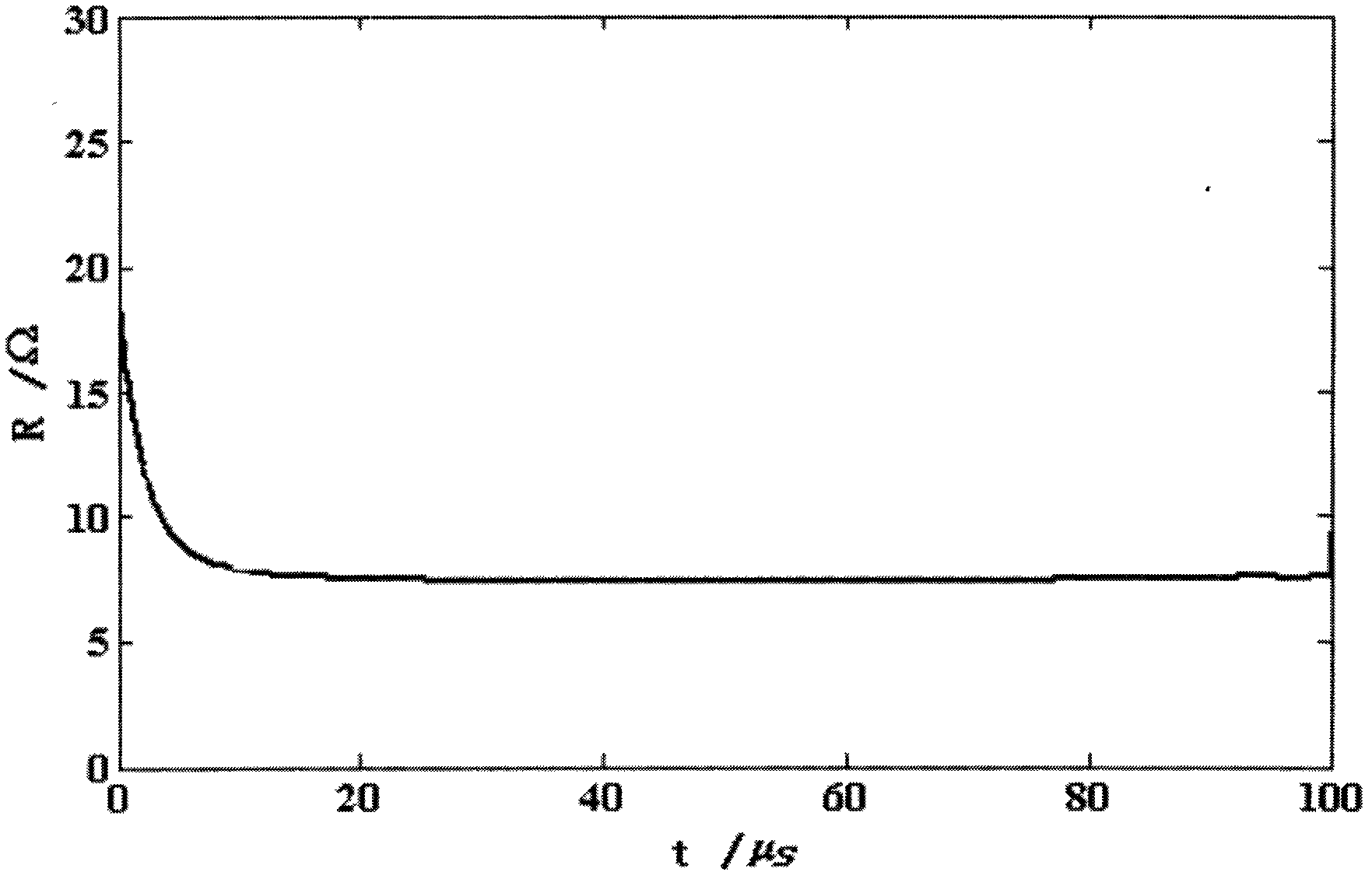
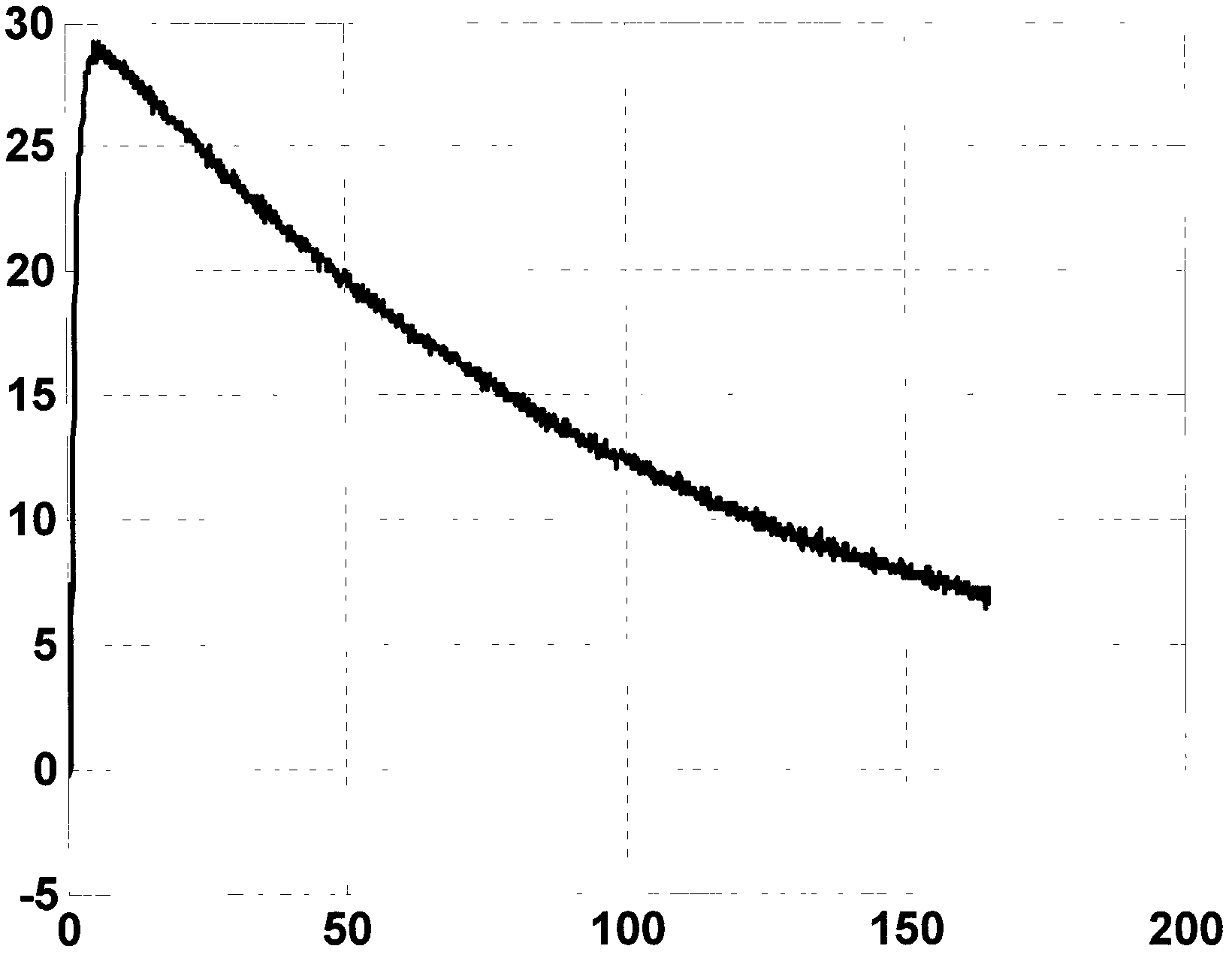
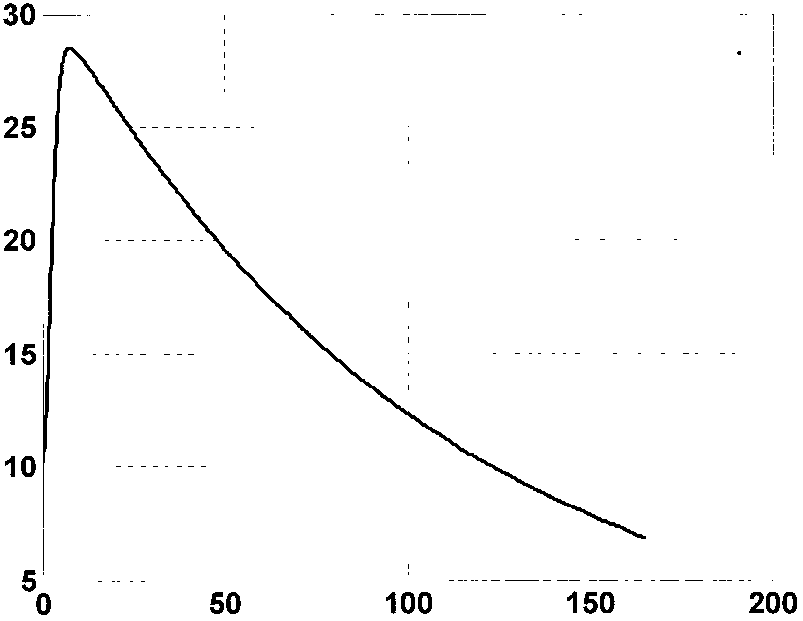

Image

  • Improved method for measuring impulse grounding resistance of electric power system
  • Improved method for measuring impulse grounding resistance of electric power system
  • Improved method for measuring impulse grounding resistance of electric power system

Examples


Embodiment Construction

[0022] The technical solution of the present invention will be described in detail below in conjunction with the drawings and embodiments.

[0023] Such as image 3 As shown, the entire test circuit consists of a current sensor 1, a digital storage oscilloscope 2, an impulse voltage divider 3, an impulse current generator 4, a current-carrying wire 5, a ground electrode G, a voltage electrode P and a current electrode C. The magnitude of the output surge current is adjusted by setting the charging voltage of the surge current generator. The current sensor is set on the current-carrying wire. The high voltage end of the impact voltage divider is connected to the current injection point of the ground electrode, and its low voltage end is connected to the voltage electrode. The storage oscilloscope is respectively connected to the signal output terminals of the current sensor and the impact voltage divider through the coaxial shielded cable to collect the signals of the current s...


PUM


Abstract

The invention relates to a method for measuring impulse grounding resistance of an electric power system, in particular to an improved method for measuring the impulse grounding resistance of the electric power system, which is used for researching the impulse characteristics of concentrated grounding electrodes with different structures. Transient stable-state impulse grounding resistance is defined as the resistance of a grounding body at the half-peak moment of impulse current. The improved method for measuring the impulse grounding resistance of the electric power system comprises the following steps: firstly, generating the impulse current by an impulse current generator and injecting the impulse current into the earth; acquiring voltages at both ends of the concentrated grounding electrodes with different structures and voltage electrodes and current at a current injection point by taking an impulse voltage divider and a current sensor as conversion devices by utilizing a digital storage oscilloscope; and processing acquired data through matrix laboratory (MATLAB) software to obtain the transient stable-state impulse grounding resistance of the grounding electrode under certain impulse current. The transition-state impulse grounding resistance disclosed by the invention is capable of actually reflecting the current dispersing capacity of the grounding body under the impulse current and is capable of actually describing the maximum potential rise of the grounding body under the amplitude of the impulse current.

Description

Technical field [0001] The invention relates to a method for measuring the impact grounding resistance of a power system, in particular to an improved measurement method for the impact grounding resistance of a power system, which is used for studying the impact characteristics of centralized grounding electrodes with different structures. Background technique [0002] Grounding resistance refers to the resistance when power frequency or DC current flows, usually called power frequency (or DC) grounding resistance; for lightning protection grounding, the resistance when lightning impulse current flows is called impact grounding resistance. [0003] In order to study the impact characteristics of lightning current leakage through the grounding body, people have been devoting themselves to evaluating it by obtaining the impact grounding resistance. The specific methods are as follows: [0004] A. Establish a mathematical and physical model for the specific grounding device, an...

Claims


Application Information

Patent Timeline
IPC IPC(8): G01R27/20
Inventor 喻剑辉韩学民彭梦飞徐斌夏长征周文俊
Owner 国网安徽省电力有限公司巢湖市供电公司
Why Eureka
Try Eureka