Eureka AIR delivers breakthrough ideas for toughest innovation challenges, trusted by R&D personnel around the world.

Optical axis levelling and gravity unloading supporting method of large diameter lightweight mirror

A lightweight mirror, gravity unloading technology, applied in the field of optics, to achieve the effect of stable support state

Active Publication Date: 2012-05-02
BEIJING RES INST OF SPATIAL MECHANICAL & ELECTRICAL TECH
View PDF2 Cites 11 Cited by
  • Summary
  • Abstract
  • Description
  • Claims
  • Application Information

AI Technical Summary

Problems solved by technology

[0005] The technical problem of the present invention is: to overcome the deficiency that the previous sling form can only provide the support of the lower semicircle, and to provide a method of horizontal gravity unloading of the optical axis of the large-diameter light mirror, which reduces the deformation of the light mirror under the gravity environment

Method used


Image

  • Optical axis levelling and gravity unloading supporting method of large diameter lightweight mirror
  • Optical axis levelling and gravity unloading supporting method of large diameter lightweight mirror

Examples


Embodiment Construction

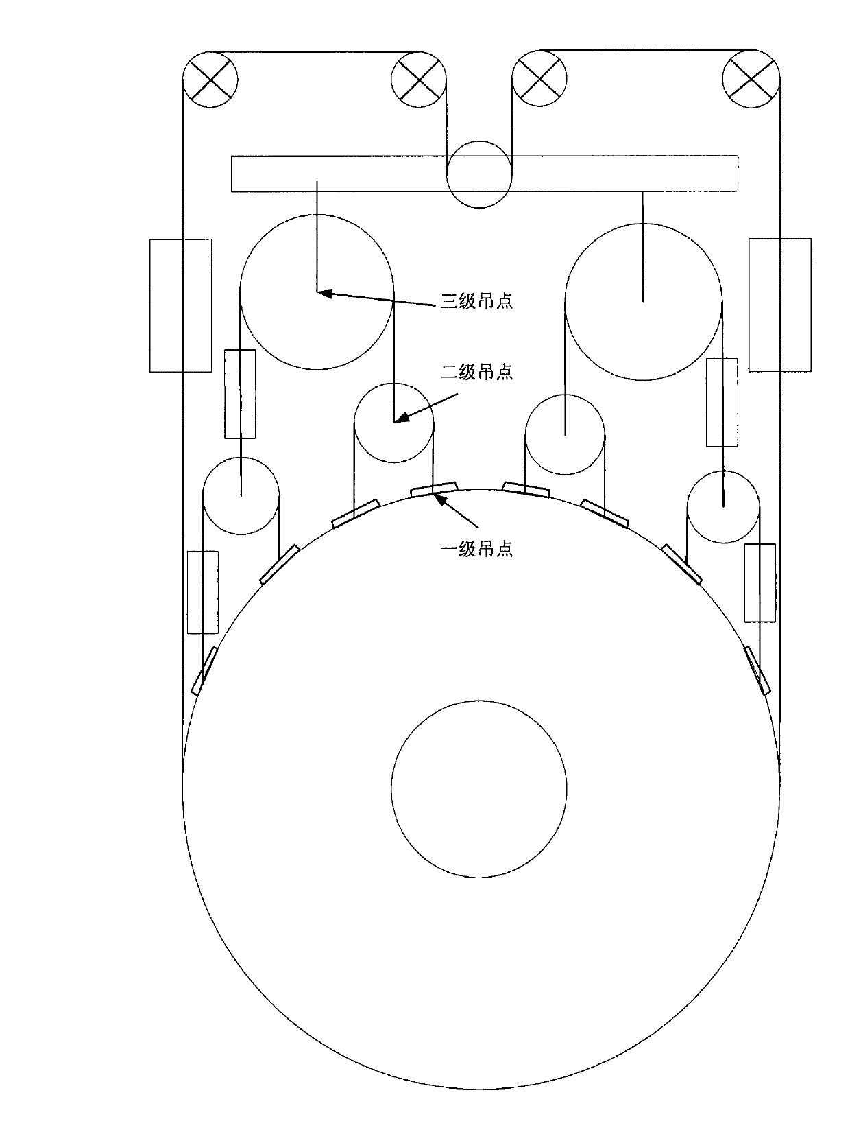
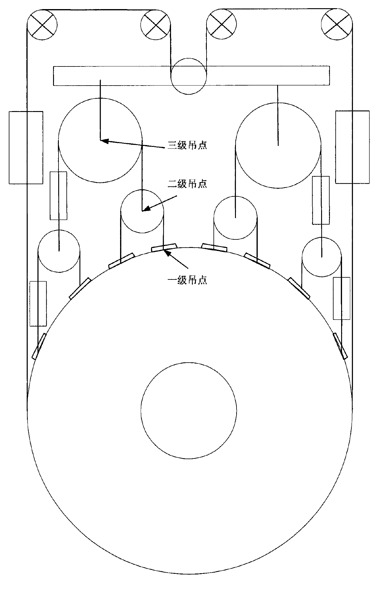
[0021] Such as figure 1 Shown is the schematic diagram of the method of the present invention, and the frocks involved in the method of the present invention include slings, large-caliber light mirrors, suspension points, wire ropes, counterweights, movable pulleys, lever beams, fixed pulleys, etc.

[0022] The main steps are as follows:

[0023] (1) Fix the first fixed pulley, the second fixed pulley, the third fixed pulley and the fourth fixed pulley sequentially from left to right in the horizontal direction, and arrange the first movable pulley below the second fixed pulley and the third fixed pulley; The distance between the outer tangent of a certain pulley and the outer tangent of the fourth fixed pulley is equal to the diameter of the disc reflector, and the first movable pulley is located on the perpendicular bisector of the center line of the second fixed pulley and the third fixed pulley, The first moving pulley is fixed in the middle of the lever beam;

[0024] (...


PUM


Abstract

The invention provides an optical axis levelling and gravity unloading supporting method of a large diameter lightweight mirror. The method has the following advantages: the characteristics that the pulley block lifting ropes can adaptively shift and the provided pull is changeless are utilized to realize that not only supporting force but also lifting and pulling forces can be provided to the large diameter lightweight mirror in the level state of the optical axis and the supporting force and the lifting and pulling forces can realize adaptive equilibrium; deformation of the large diameter lightweight mirror caused by gravity effect can be furthest reduced in the environment of ground gravity field, thus improving the optical detection precision; and meanwhile, the method has terrific engineering feasibility.

Description

technical field [0001] The invention belongs to the field of optics and relates to a mirror supporting method. Background technique [0002] The surface inspection of large-diameter optical parts is an important part of optical processing, which directly determines the processing accuracy of optical parts. However, the large-diameter optical parts used in space remote sensors need to adopt lightweight design, and their absolute rigidity is low. Under the ground gravity environment, different support forms and support states will cause different gravity deformation results. [0003] In 2001, Volume 28, No. 5, "Optoelectronic Engineering" published a paper entitled "Finite Element Analysis of Large-Aperture Lightweight Mirror Support", in which the finite element analysis of the gravity deformation of the lightweight mirror was carried out, and it was proposed that In order to use the form of mercury sling to provide support for the horizontal state of the optical axis of the...

Claims


Application Information

Patent Timeline
Patent Type & Authority Applications(China)
IPC IPC(8): G02B7/182G02B7/198
Inventor 周于鸣闻广泉赵野王海超
Owner BEIJING RES INST OF SPATIAL MECHANICAL & ELECTRICAL TECH
Why Eureka
Eureka Blog
Learn More