Layered-modeling device and method using said device for manufacturing three-dimensional objects

一种层叠造型、三维形状的技术,应用在制造辅助装置、加工制造、制造工具等方向,能够解决烟气易充满腔室、加工精度降低、光束输出或聚光度降低等问题

Inactive Publication Date: 2012-05-02
PANASONIC CORP
View PDF7 Cites 35 Cited by
  • Summary
  • Abstract
  • Description
  • Claims
  • Application Information

AI Technical Summary

Problems solved by technology

[0004] However, in such a manufacturing method, the chamber is easily filled with fumes generated during sintering or melting and solidification, and the fumes are also likely to adhere to the windows.
Although shielding gas is supplied into the chamber, it takes time to replace the flue gas with the shielding gas, and the light beam is scattered due to the filled fume or the fume adhering to the window, so that the output or concentration of the light beam may decrease, or the The problem that the accuracy of the irradiation position of the beam is lowered and the machining accuracy is lowered
In addition, the temperature of the window rises due to the absorption of the light beam by the smoke adhering to the window, and when the window is thermally deformed, there is a problem that the accuracy of the irradiation position is further reduced.

Method used


Image

  • Layered-modeling device and method using said device for manufacturing three-dimensional objects
  • Layered-modeling device and method using said device for manufacturing three-dimensional objects
  • Layered-modeling device and method using said device for manufacturing three-dimensional objects

Examples


Embodiment Construction

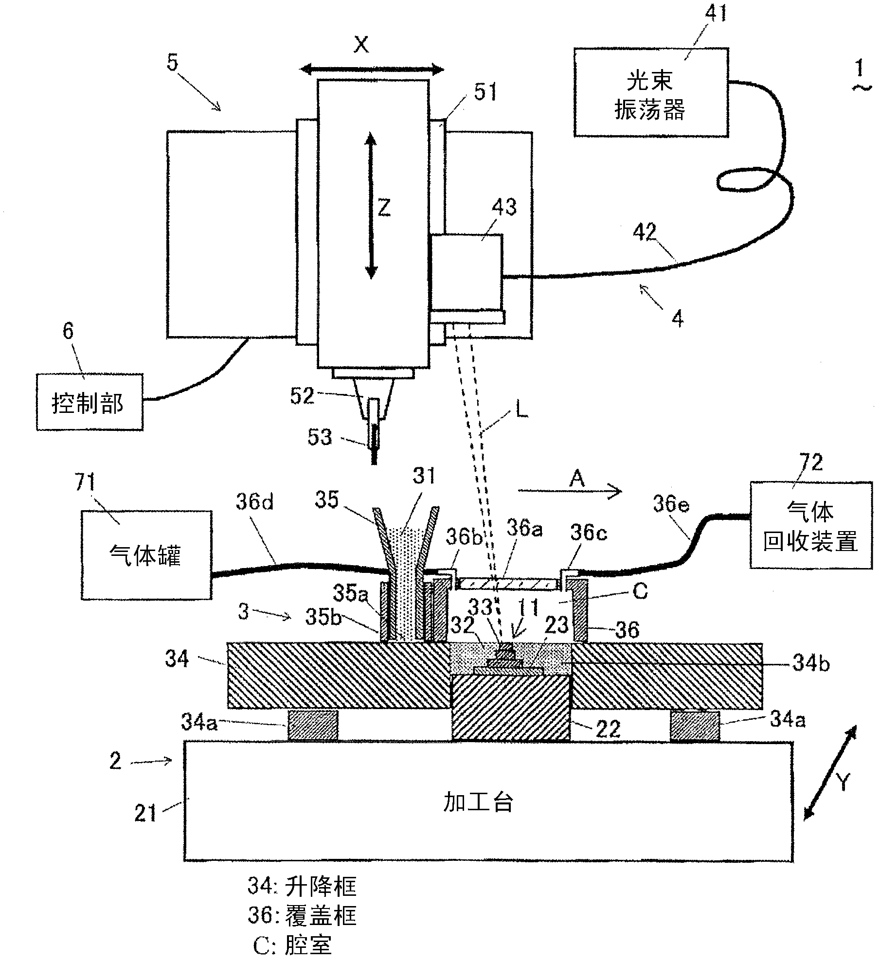
[0083] A method of manufacturing a three-dimensional modeled object according to an embodiment of the present invention will be described with reference to the drawings. figure 1 The structure of the lamination molding apparatus (hereinafter referred to as "this apparatus") used in this production method is shown. This device 1 includes: a molding unit 2 for molding a three-dimensional shaped object 11; a powder layer forming unit (powder layer forming mechanism) 3 for supplying material powder 31 to form a powder layer 32; and forming a powder layer 32 by irradiating a beam L. The beam irradiation unit 4 for the solidified layer 33 ; the cutting and removal unit 5 for cutting the periphery of the molded object 11 ; and the control unit 6 for controlling the operation of each unit. By irradiating the light beam L, the powder layer 32 is sintered or melt-solidified to form the solidified layer 33 . This apparatus 1 further includes: a gas tank (shielding gas supply mechanism) ...


PUM

PropertyMeasurementUnit
particle diameteraaaaaaaaaa
porosityaaaaaaaaaa

Abstract

Provided is a method for manufacturing three-dimensional objects. Said method can easily remove fumes from a chamber and improves the fabrication precision and the irradiation-positioning precision of a light beam. A layered-modeling device (1) is provided with: a powder-layer formation unit (3); a light-beam irradiation unit (4); a fixed base (22) on which a powder layer (32) is formed; a raising / lowering frame (34) which surrounds the base (22) and can move freely up and down; a covering frame (36) which is disposed above the raising / lowering frame (34), thereby forming a chamber (C); and a gas tank (71) which supplies an atmosphere gas. The top surface of the covering frame has a window (36a) through which the light beam passes, and the bottom surface of the covering frame is open. By lowering the raising / lowering frame (34), the volume of the chamber (C) is decreased, and fumes which were generated inside the covering frame (36) are exhausted and replaced with the atmosphere gas. The decrease in the volume of the chamber (C) allows the fumes to be removed easily, and improves the fabrication precision and irradiation-positioning precision of the light beam (L).

Description

technical field [0001] The present invention relates to a lamination molding device for irradiating an inorganic or organic powder material with a beam of light and a method for manufacturing a three-dimensional shaped object. Background technique [0002] Conventionally, there is known a manufacturing method in which a three-dimensional shaped object is manufactured by repeating the process of irradiating a powder layer formed of material powder with a beam of light to sinter or melt-solidify the powder layer to form a solidified layer , form a new powder layer on the solidified layer and irradiate the beam to form a solidified layer. [0003] In such a manufacturing method, in order to improve the processing accuracy of the molded object, there is known a manufacturing method using a molding device including: a fixed base; a lifting frame that surrounds the base and can be raised and lowered freely; The upper surface has a window through which light beams pass, and the lo...

Claims


Application Information

Patent Timeline
Patent Type & Authority Applications(China)
IPC IPC(8): B22F3/16B22F3/105B29C67/00
CPCB29C67/0085B22F3/1055B29C67/0077B22F2999/00B22F2003/1056B23P15/00B29C64/153B33Y30/00B33Y40/00B29C64/364B29C64/25B29C64/268Y02P10/25B22F10/32B22F12/33B22F10/77B22F10/28B22F12/70B22F12/90B22F10/50B22F12/41B22F2201/00B33Y50/02
Inventor 阿部谕吉田德雄东喜万不破勋
Owner PANASONIC CORP
Why Eureka
Try Eureka