
Cascade accelerator

An accelerator and cascading technology, applied in DC voltage accelerators, electrical components, accelerators, etc., can solve problems such as breakdown and energy limitation, and achieve the effect of simple geometry, simple structure, and compact structure

Inactive Publication Date: 2014-09-10
SIEMENS AG
View PDF5 Cites 0 Cited by
  • Summary
  • Abstract
  • Description
  • Claims
  • Application Information

AI Technical Summary

Problems solved by technology

Here, however, there is a risk of electrical breakdown (breakdown voltage in air: 3 kV / mm), especially in the cascade accelerators specified at normal atmospheric pressure, so that the maximum particle energy is undesirably restricted

Method used


Image

  • Cascade accelerator
  • Cascade accelerator
  • Cascade accelerator

Examples


Embodiment Construction

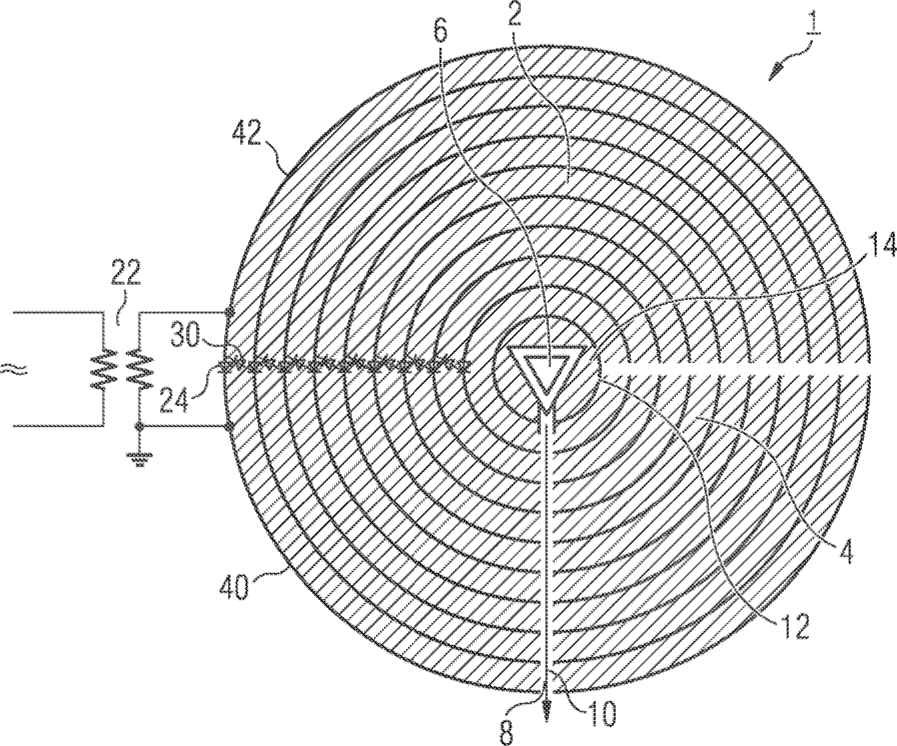
[0022] according to figure 1 The cascade generator 1 has a first group 2 and a second group 4 consisting of electrodes in the shape of hollow hemispheres. They are arranged concentrically around the particle source 6 .

[0023] Passing through the second electrode set 4 is an acceleration channel 8 aligned with the particle source 6 and allowing extraction of a particle stream 10 emanating from the particle source and subjected to a high acceleration voltage from a hemispherical shaped high voltage electrode 12 .

[0024] In order to prevent the internal breakdown by the high voltage of the high voltage electrode 12 on the particle source 6, the particle source 6 can be completely embedded in the solid or liquid insulating material 14, so that the high voltage electrode 12 and the The spaces between the particle sources 6 are filled with insulating material 14 . As a result, a particularly high voltage can be provided at the high-voltage electrode 12, which can generate a pa...


PUM


Abstract

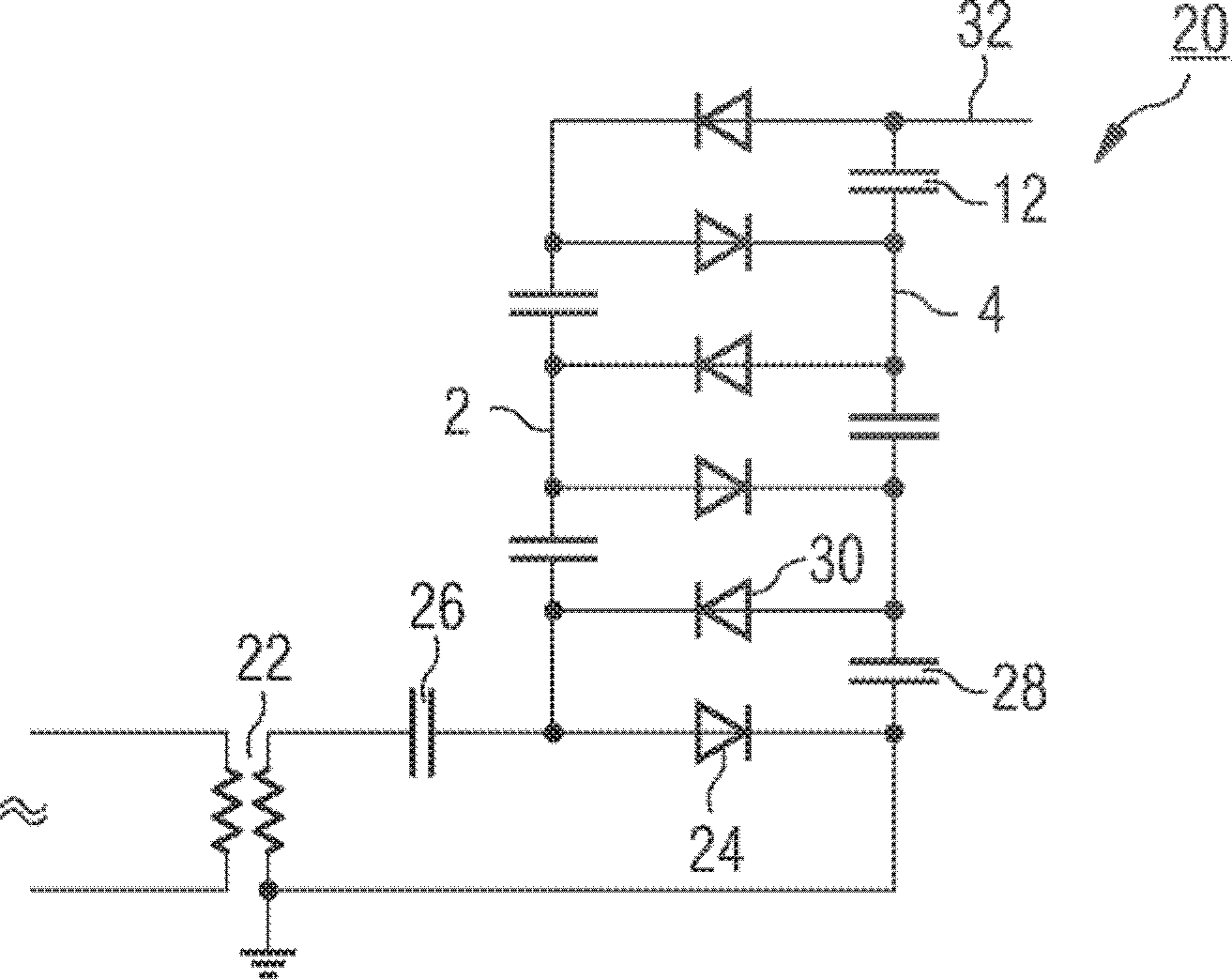
The invention relates to a cascade accelerator (1) having two sets (2, 4) of capacitors (26, 28) connected in series in each case via diodes (24, 30) in a Glenach cascade (20) ), the cascade accelerator should have particularly high achievable particle energies in the case of a compact design. To this end, the cascade accelerator comprises an accelerating channel directed at the particle source (6) arranged in the region of the electrode with the highest voltage (12) via openings in the electrodes of a set of capacitors (2) (8), wherein the electrodes are insulated from each other, except for the acceleration channel (8), by means of a solid or liquid insulating material (14).

Description

technical field [0001] The invention relates to a cascade accelerator with two sets of capacitors connected in each case in series via diodes in the manner of a Greinach cascade. The invention also relates to a radiotherapy device with such a cascade accelerator. Background technique [0002] Ionizing radiation is used in medical radiotherapy in order to treat a condition or delay the progression of a condition. Primarily gamma rays, X-rays, and electrons are high-energy radiation used for ionization. [0003] In order to generate electron beams, particle accelerators are usually used for direct treatment or for the generation of X-rays. In particle accelerators, charged particles are brought to high velocity and thus have kinetic energy by an electric field, where the electric field of several accelerator types is generated by electromagnetic induction in a changing magnetic field. In this case, the particle acquires a kinetic energy that corresponds to several times its...

Claims


Application Information

Patent Timeline
Patent Type & Authority Patents(China)
IPC IPC(8): H05H5/06
CPCH05H5/06Y10T29/49002
Inventor O.希德
Owner SIEMENS AG
Learn More