Automatic locking mechanism and automatic locking filature provided with same

An automatic locking, pneumatic screwdriver technology, applied in metal processing, metal processing equipment, manufacturing tools and other directions, can solve the problems of low speed, easy to heat signal controllability, can not be used in the field of automatic locking and payment, to improve the level of automation Effect

Active Publication Date: 2012-05-09
ANHUI TATFOOK TECH CO LTD
View PDF5 Cites 27 Cited by
  • Summary
  • Abstract
  • Description
  • Claims
  • Application Information

AI Technical Summary

Problems solved by technology

[0005] In order to solve the shortcomings of the electric screwdriver in the prior art, such as low speed, easy heat and overload, and poor controllability of the control signal of the pneumatic screwdriver, which cannot be used in the field of automatic locking, the present invention optimizes the mechanical structure of the automatic locking device. Design, provides An automatic locking mechanism that has the advantages of stable control signal of an electric screwdriver and high speed of a pneumatic screwdriver, and can realize high-speed controllability

Method used


Image

  • Automatic locking mechanism and automatic locking filature provided with same
  • Automatic locking mechanism and automatic locking filature provided with same
  • Automatic locking mechanism and automatic locking filature provided with same

Examples


Embodiment Construction

[0028] The present invention will be described in detail below in conjunction with the accompanying drawings and embodiments.

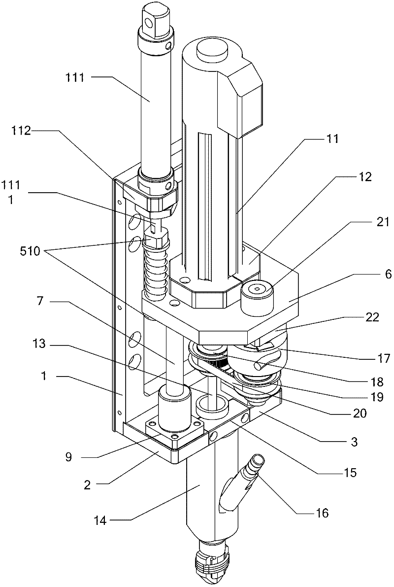
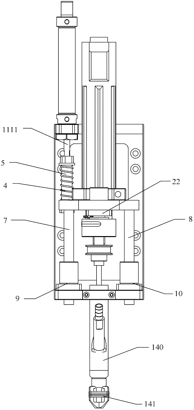
[0029] like figure 1 and figure 2 As shown, the automatic locking mechanism of the present invention mainly includes a mounting base plate 1, a first bearing mounting plate 2, a second bearing mounting plate 3, a pushing assembly, a pressing assembly, a screw-in assembly and a control assembly, and the pushing assembly drives the pressing assembly Moving vertically downward, the compression component drives the screw-in component to engage the compression screw, the screw-in component screws into the locking screw, and the control component controls the stop of the screw-in component when it detects that the screw is locked and stops rotating.

[0030] The push assembly is fixed on the installation base plate 1, the push assembly includes a locking cylinder 111 and a cylinder mounting plate 112, the locking cylinder 11 includes a push rod 1111, the ...


PUM


Abstract

The invention discloses an automatic locking mechanism and an automatic locking filature provided with the same. The automatic locking mechanism mainly comprises an installation bottom plate, a first bearing installation plate, a second bearing installation plate, a push assembly, a compression assembly, a precession assembly and a control component, wherein the first bearing installation plate and the second bearing installation plate are fixedly arranged relative to the installation bottom plate; the push assembly is fixed on the installation bottom plate; the compression assembly is arranged on the first bearing installation plate and the second bearing installation plate; the push assembly is used for driving the compression assembly to move vertically downwards; and the precession assembly comprises a pneumatic screw driver for driving a screw to rotate for locking. In the automatic locking mechanism, the working condition of the pneumatic screw driver is controlled through the control assembly, a synchronous belt wheel and an encoder, so that the controllability of a torque signal of the pneumatic screw driver is realized, and the automatic locking speed is greatly increased.

Description

【Technical field】 [0001] The invention relates to the field of machining screw locking, in particular to an automatic locking mechanism and an automatic locking screw machine using the automatic locking mechanism. 【Background technique】 [0002] At present, in the manufacturing industries such as electronic machinery and toy furniture, screw (screw and stud) assembly operations are widely used. In the past, most of the screw assembly operations were manual operations. They were manually placed in the screw holes, and then locked one by one with a screwdriver. tight, low production efficiency, high labor intensity and other disadvantages, which is not conducive to the expansion of the production scale of enterprises and the improvement of production efficiency. With the development of science and technology and the progress of production technology, more and more automation equipment has been put into production line operations. Automation operations have replaced manual simp...

Claims


Application Information

Patent Timeline
Patent Type & Authority Applications(China)
IPC IPC(8): B23P19/06
Inventor 吕战争陈宗孟潘启瑜王细冬
Owner ANHUI TATFOOK TECH CO LTD
Why Eureka
Try Eureka