
Powder spreading device for rapid forming equipment

A technology of forming equipment and powder spreading device, which is applied to the component field of rapid forming equipment, can solve the problems of difficult adjustment of powder spreading area, difficult powder restraint, complicated structure, etc., and achieves the effects of simple control, low cost, and simple and compact structure.

Active Publication Date: 2012-05-09
NORTHWEST INSTITUTE FOR NON-FERROUS METAL RESEARCH
View PDF5 Cites 18 Cited by
  • Summary
  • Abstract
  • Description
  • Claims
  • Application Information

AI Technical Summary

Problems solved by technology

[0005] The technical problem to be solved by the present invention is to provide a powder spreading device for rapid prototyping equipment in view of the deficiencies in the above-mentioned prior art, which has a simple structure, easy assembly and disassembly of various parts, easy adjustment and control, and can be independently modularized It works quickly and spreads powder quickly and has high reliability, which can solve the defects of existing powder spreading devices such as difficult powder restraint, complex structure, and difficulty in adjusting the powder spreading area.

Method used


Image

  • Powder spreading device for rapid forming equipment
  • Powder spreading device for rapid forming equipment
  • Powder spreading device for rapid forming equipment

Examples


Embodiment Construction

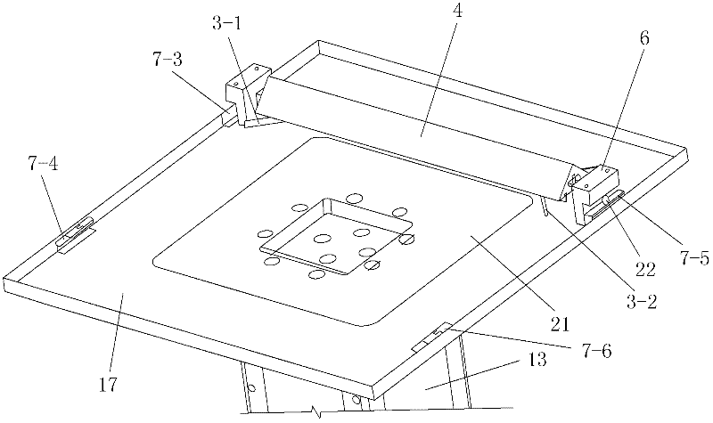
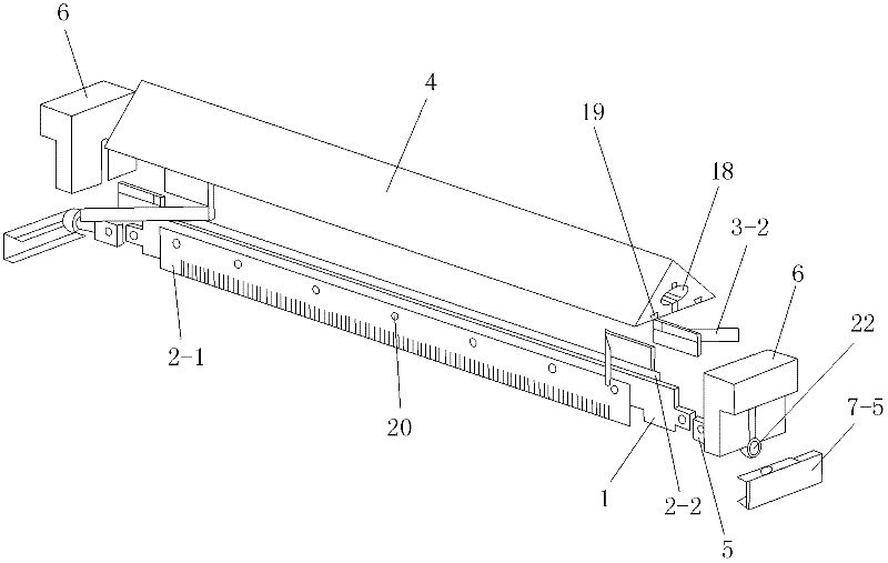
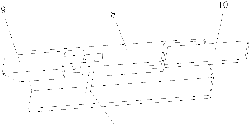
[0047] Such as figure 1 , figure 2 and Figure 5 As shown, the present invention includes a moving mechanism that is driven by a driving mechanism to move back and forth horizontally and linearly on the forming work platform 17 of the rapid prototyping equipment, a scraper mechanism that is fixedly installed at the bottom of the moving mechanism, and a scraper mechanism that is movably installed on the moving mechanism. The left side wing 3-1 and the right side wing 3-2 on the left and right sides of the bottom of the mechanism, the left side wing 3-1 and the right side wing 3-2 have the same structure and they are arranged symmetrically on the scraper mechanism left and right sides. The moving mechanism includes a horizontally arranged push block, a connecting rod 1 installed at the bottom of the push block, and a left traveling mechanism and a right traveling mechanism respectively symmetrically installed at the left and right ends of the connecting rod 1. The connecting ...


PUM


Abstract

The invention discloses a powder spreading device for rapid forming equipment, comprising a moving mechanism, a scraping plate mechanism, a left-side wing and a right-side wing, wherein the moving mechanism does horizontal-linear reciprocating movement back and forth on a forming working platform; the scraping plate mechanism is fixedly arranged at the bottom part of the moving mechanism; the left-side wing and the right-side wing are movably arranged at the left side and the right side of the bottom part of the moving mechanism; the moving mechanism comprises a pushing block, a connecting rod, a left traveling mechanism and a right traveling mechanism, wherein the connecting rod is arranged at the bottom part of the pushing block; the left traveling mechanism and the right traveling mechanism are respectively and symmetrically arranged at the left end part and the right end part; the scraping plate mechanism comprises a front scraping plate and a rear scraping plate which are symmetrically arranged; and both the left-side wing and the right-side wing are splayed side wings II which are consists of two inclined side plates III and can move horizontally towards left and right alongthe scraping plate mechanism. In the powder spreading device, the structure is simple, the assembly and disassembly of all the parts are simple and convenient, the adjustment and control of all the parts are simple and easy, the independent modular working can be realized, the powder spreading is fast, the reliability is high, and the defects of difficult powder confinement, complex structure and difficult adjustment of powder-spreading areas and the like in the existing powder-spreading device can be solved.

Description

technical field [0001] The invention relates to a component of rapid prototyping equipment using powder as raw material and adopting a selective deposition / sintering / melting process, in particular to a powder spreading device for rapid prototyping equipment. Background technique [0002] At present, the rapid prototyping technology of parts using powder as raw material through selective deposition / sintering / melting process is a hotspot in the field of rapid manufacturing. Typical technologies include: selective laser sintering (Selective Laser Sintering, SLS), selective laser sintering Melting (Selective Laser Melting, SLM), electron beam melting (Electron Beam melting, EBM), three-dimensional printing (Three Dimensional Printing, 3DP). The technological process of the above-mentioned technologies is similar: first, a layer of raw material powder is laid on the processing plane, and then the processing source divides the powder according to the cross-sectional shape of the p...

Claims


Application Information

Patent Timeline
Patent Type & Authority Applications(China)
IPC IPC(8): B65G47/82
Inventor 赵培汤慧萍贾文鹏黄瑜贺卫卫刘海彦
Owner NORTHWEST INSTITUTE FOR NON-FERROUS METAL RESEARCH
Learn More