Water suction chamber of multistage centrifugal pump

A water-absorbing chamber and centrifugal pump technology, applied to pumps, parts of pumping devices for elastic fluids, pump components, etc., can solve problems such as prolonged production cycle, insufficient smoothness of the flow channel, and complex structure

Inactive Publication Date: 2012-05-09
KSB SHANGHAI PUMP
View PDF8 Cites 1 Cited by
  • Summary
  • Abstract
  • Description
  • Claims
  • Application Information

AI Technical Summary

Problems solved by technology

However, because of its complex structure and difficult processing, it usually needs to be cast to complete
However, during casting, defects such as blisters and pores oft

Method used


Image

  • Water suction chamber of multistage centrifugal pump
  • Water suction chamber of multistage centrifugal pump
  • Water suction chamber of multistage centrifugal pump

Examples


Embodiment Construction

[0020] The technical solution of the present invention will be further described below in conjunction with the drawings and embodiments.

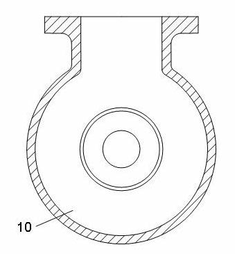
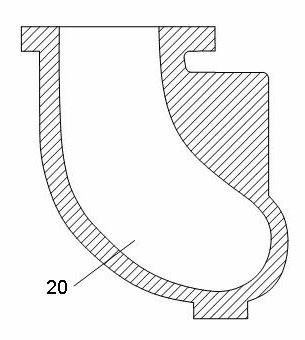
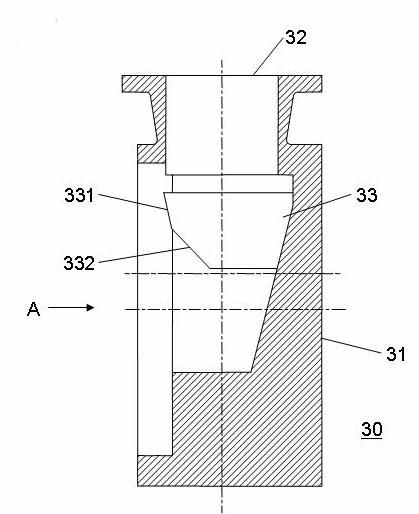
[0021] Please combine image 3 , Figure 5 As shown, the water suction chamber 30 of the multi-stage centrifugal pump of the present invention includes a housing 31, the upper end of the housing 31 is provided with a water inlet 32, and one end of the front end of the housing 31 is connected to the water inlet 1 and communicated with the inlet of the impeller 2. The difference from the prior art is that the suction chamber 30 also includes a baffle 33 that divides the liquid entering the suction chamber 30 into two parts and flows downward. The baffle 33 is arranged in the housing 31 and Located in the middle position above the shaft hole 34 (used to install the impeller shaft 3) in the housing 31. The specific structure of the deflector 33 is as follows: the upper and lower end surfaces of the deflector 33 are curved surfaces, the rear end o...


PUM

PropertyMeasurementUnit
Radiusaaaaaaaaaa

Abstract

The invention discloses a water suction chamber of a multistage centrifugal pump. The water suction chamber comprises a shell body, wherein a water inlet is disposed at the upper end of the shell body, and one end of the front end surface of the shell body is connected with a water inlet chamber and communicated with the inlet of an impeller. The centrifugal pump further comprises a flow guide plate, wherein the flow guide plate is disposed in the shell body and located at a middle position above a shaft hole in the shell body. A liquid entering in the water suction chamber can be divided into two parts flowing downwards via the flow guide plate, thereby efficiently reducing the reflux of the liquid, and benefiting to ensure the flow speed of the liquid entering in the water suction chamber to be uniform and stable. Additionally, the speed of a water flow in a whole flow passage can be kept uniform and stable via an optimized design for the flow passage of the shell body. Moreover, the water suction chamber of a multistage centrifugal pump further has the advantages of being simple in structure and easy in processing.

Description

Technical field [0001] The invention relates to a centrifugal pump, and more specifically, to a suction chamber of a multistage centrifugal pump. Background technique [0002] The suction chamber is the flow-through part from the pump inlet to the impeller inlet, and its function is to introduce liquid into the impeller according to the required conditions. At present, the common suction chambers on multi-stage centrifugal pumps are divided into annular suction chambers and spiral suction chambers. [0003] See figure 1 As shown, the annular suction chamber 10 is a suction chamber with the same body shape and cross-sectional area, and its structure is simple and symmetrical. For example, the application number 96207955.3, the suction chamber disclosed in the Chinese patent entitled Double-volute multi-stage pump inlet section is the *annular suction chamber. However, the suction chamber 10 of this structure cannot guarantee that the impeller inlet has an axially symmetric and uni...

Claims


Application Information

Patent Timeline
IPC IPC(8): F04D29/42
Inventor 叶亚丽施永涛孙刚
Owner KSB SHANGHAI PUMP
Why Eureka
Try Eureka