Variable damping control and buffering system

A damping control and buffering system technology, applied in springs, shock absorbers, springs/shock absorbers, etc., can solve the problems of high machining accuracy, large space occupation, oil leakage, etc., and achieve effective damping adjustment and control, pressure control Simplicity, the effect of reducing manufacturing costs

Active Publication Date: 2013-10-09
JOINTECH (SUZHOU) VEHICLE SYST CO LTD
View PDF8 Cites 0 Cited by
  • Summary
  • Abstract
  • Description
  • Claims
  • Application Information

AI Technical Summary

Problems solved by technology

[0003] In the prior art, the hydraulic buffer system has two structures, the built-in oil circuit and the external oil circuit. The built-in oil circuit has a high degree of integration and takes up little space, but has high processing requirements and complicated maintenance; the hydraulic buffer system structure with the external oil circuit It is more complicated and takes up a lot of space, but it has been widely used in articulated vehicles due to its convenient maintenance. For example, Chinese patent CN201086607 discloses a hydraulic buffer device with an external oil circuit, which controls hydraulic damping through the rotation of the mandrel, thereby changing the buffer Damping hydraulic control system, although this control system can form different damping according to the change of the included angle of the vehicle, which has an obvious effect in preventing the shearing of the front and rear vehicles, but the structure of the mandrel is complicated and the machining accuracy is high. The cost is high, the installation and connection are complicated, and sometimes there are disadvantages such as oil leakage, valve core stuck or electrical system failure
[0004] At the same time, because the buffer damping in the prior art cannot be accurately controlled, drivers often have accidents due to the large turning angle when driving an articulated vehicle, especially when making a large turn, causing casualties and property losses

Method used


Image

  • Variable damping control and buffering system
  • Variable damping control and buffering system
  • Variable damping control and buffering system

Examples


Embodiment Construction

[0018] In order to understand the technical content of the present invention more clearly, the following examples are given in detail.

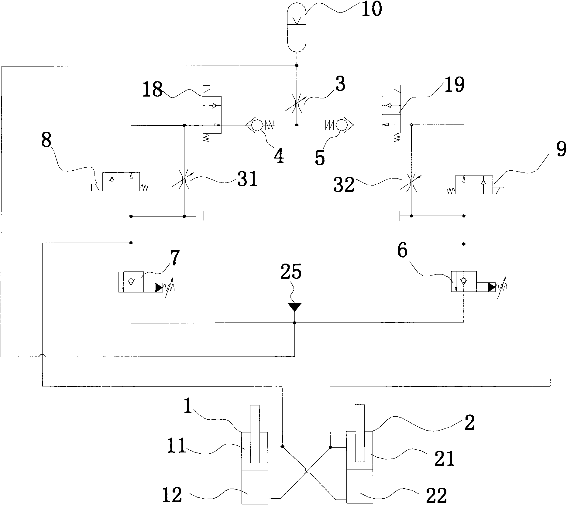
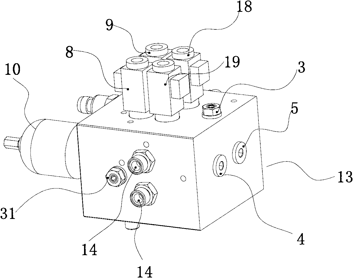
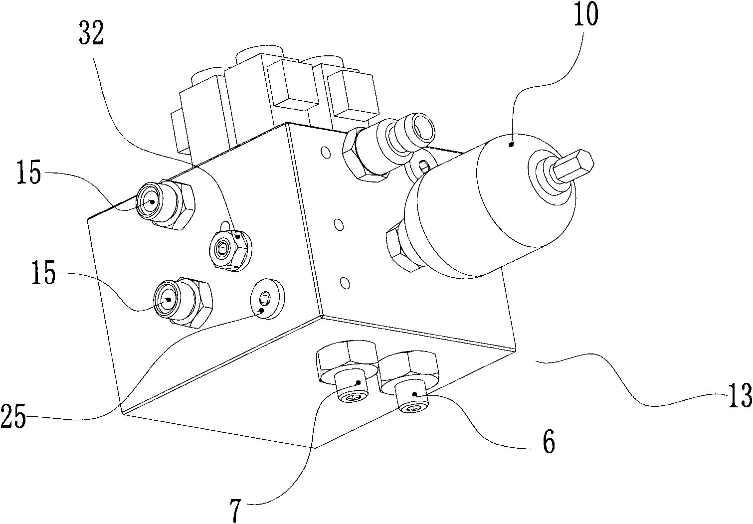
[0019] Such as Figure 1-Figure 3 As shown, the present invention relates to a variable damping control buffer system, including a first hydraulic cylinder 1 and a second hydraulic cylinder 2, the first hydraulic cylinder 1 is divided into a rod chamber 11 and a rodless chamber 12 by a piston, so The second hydraulic cylinder 2 is divided into a rod chamber 21 and a rodless chamber 22 by the piston. The variable damping control buffer system also includes a basic pressure regulating valve 3, a first pressure regulating valve 31, a second pressure regulating valve 32, The first one-way valve 4, the second one-way valve 5, the first one-way overflow valve 6 and the second one-way overflow valve 7, the second hydraulic cylinder rodless cavity 22, the first hydraulic cylinder rod cavity 11. The first pressure regulating valve 31, the first one-w...


PUM


Abstract

The invention relates to a variable damping control and buffering system, which belongs to the technical field of hydraulic buffering, and includes a first hydraulic cylinder and a second hydraulic cylinder, as well as a base pressure regulating valve, a first pressure regulating valve, a second pressure regulating valve, a first one-way valve, a second one-way valve, a first one-way overflow valve and a second one-way overflow valve, wherein a second hydraulic cylinder rodless cavity, a first hydraulic cylinder rod chamber, the first pressure regulating valve, the first one-way valve, the base pressure regulating valve, the first one-way overflow valve, a second hydraulic cylinder rod chamber, a first hydraulic cylinder rodless cavity are sequentially connected in series to form a first oil circuit; and the first hydraulic cylinder rodless cavity, the second hydraulic cylinder rod chamber, the second pressure regulating valve, the second one-way valve, the base pressure regulating valve, the second one-way overflow valve, the first hydraulic cylinder rod chamber and the second hydraulic cylinder rodless cavity are sequentially connected in series through a pipeline to form a second oil circuit. The variable damping control and buffering system has unique design, convenience for maintenance, capability of damping regulation and control, and the functions of locking and safety protection.

Description

technical field [0001] The invention relates to the technical field of damping and shock absorbing control systems for vehicles, in particular to a variable damping control buffer system. Background technique [0002] With the rapid development of my country's automobile manufacturing industry, various vehicle manufacturing industries are also advancing by leaps and bounds. Articulated buses are gradually popularized in large and medium-sized cities in China due to their large passenger capacity and high utilization coefficient. Articulated buses are generally composed of front and rear carriages and a chassis articulation system connecting the front and rear carriages, among which the hydraulic buffer system in the chassis articulation system is the key factor restricting the performance of articulated cars; the hydraulic buffer system of articulated buses generally consists of two hydraulic cylinders, one hydraulic control The hydraulic cylinder is controlled by the hydrau...

Claims


Application Information

Patent Timeline
Patent Type & Authority Patents(China)
IPC IPC(8): F16F9/50
Inventor 郝庆军
Owner JOINTECH (SUZHOU) VEHICLE SYST CO LTD
Why Eureka
Try Eureka