Lens driving device and camera module

A lens driving device and lens technology, applied in the direction of cameras, projection devices, printing devices, etc., can solve the problems of larger device size, poor friction, higher cost, etc., and achieve the effect of suppressing tilt

Inactive Publication Date: 2012-05-09
PANASONIC CORP
View PDF4 Cites 12 Cited by
  • Summary
  • Abstract
  • Description
  • Claims
  • Application Information

AI Technical Summary

Problems solved by technology

Therefore, due to the difference in frictional force between the shaft portion and the hole of the bracket into which the shaft portion is inserted, there may be a problem that the bracket moves obliquely, that is, so-called tilting.
[0006] In addition, since four magnets are attached to the holder and two shafts are arranged on the base, the number of parts increases, the cost increases, and the size of the device also increases

Method used


Image

  • Lens driving device and camera module
  • Lens driving device and camera module
  • Lens driving device and camera module

Examples


Embodiment Construction

[0057] Hereinafter, embodiments of the present invention will be described with reference to the drawings.

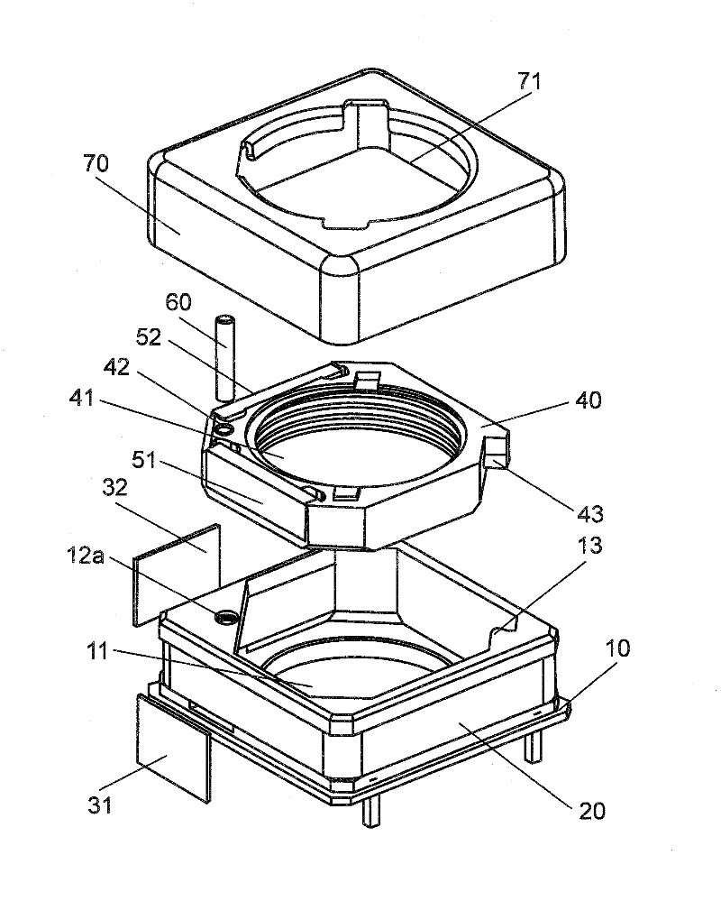
[0058] figure 1 It is an exploded perspective view of the lens drive unit. In this embodiment, the lens is not shown for convenience of description.

[0059] refer to figure 1 , The lens driving device includes: a base 10 , a coil 20 , magnetic plates 31 , 32 , a bracket 40 , magnets 51 , 52 , a shaft 60 , and a cover 70 .

[0060] The coil 20 is a continuous structure, which is wound in one direction on the side of the base body 10 . The magnets 51, 52 are mounted on both sides of the bracket 40, respectively. The cross section of the shaft portion 60 is circular and has a diameter slightly smaller than the inner diameter of the hole 42 of the bracket 40 .

[0061]The cover body 70 has a box shape with an open bottom. The cover 70 has a square shape with chamfered corners in plan view. The outer shape of the cover body 70 in plan view is substantially the same a...


PUM


Abstract

A lens driving device prevents its holder from tilting while driving the lens, and has a small number of components, low cost, and small size. The lens driving device includes a base, a holder, magnets, and magnetic plates. The base includes a projection having a hook-shaped cross section. The holder includes a rotation inhibitor which comes into contact with the projection of the base. The holder is supported to the base by one shaft. One magnetic plate is located further from the shaft than the center of the magnet is. The other magnetic plate is located closer to the shaft than the center of the magnet is. The magnetic forces generated between the magnetic plates and the magnets make the holder subjected to a torque on the shaft. The torque allows the rotation inhibitor to be slightly pressed against the projection.

Description

technical field [0001] The present invention relates to a lens driving device and a camera module, and more particularly to an autofocus lens driving device mounted on a compact camera or the like, and a camera module mounted thereon. Background technique [0002] Conventionally, a camera module is mounted on a mobile phone or the like. This camera module is equipped with a lens driving device for realizing focus adjustment. The lens driving device can displace the lens along the optical axis according to the control signal. Accordingly, it is possible to perform focus adjustment on the subject. [0003] For example, Japanese Patent Application Laid-Open No. 2009-69611 shows a mountable moving magnet lens driving device as an autofocus driving device for a camera lens. In this lens driving device, four magnets are attached around a holder holding a lens. On the base, two shafts that guide the holder so that the holder can be displaced in the optical axis direction of the...

Claims


Application Information

Patent Timeline
Patent Type & Authority Applications(China)
IPC IPC(8): G02B7/09G03B13/36G03B17/12
CPCG03B2205/0069G03B3/10G02B7/08G03B17/02
Inventor 大石杰山下博司中岛三生太田哲
Owner PANASONIC CORP
Why Eureka
Try Eureka