Optical fiber sensing device based on optical fiber bending deformation

A technology of optical fiber sensing and optical fiber, which is applied in the direction of using optical devices to transmit sensing components, measuring devices, and measuring electrical variables. problems, to achieve the effect of flexible use, convenient processing and simple structure

Inactive Publication Date: 2012-05-16
XIAN JINHE OPTICAL TECH
View PDF1 Cites 12 Cited by
  • Summary
  • Abstract
  • Description
  • Claims
  • Application Information

AI Technical Summary

Problems solved by technology

There are few deformed teeth, and the length of the sensing fiber between the deformed teeth is short, so that its ability to collect data is poor. The bending curvature of the sensing fiber is small, resulting in a short service life. The collected data is either high in accuracy and small in dynamic range, or has a large dynamic range. Low precision, unable to meet the requirements of practical applications

Method used


Image

  • Optical fiber sensing device based on optical fiber bending deformation
  • Optical fiber sensing device based on optical fiber bending deformation
  • Optical fiber sensing device based on optical fiber bending deformation

Examples


Embodiment 1

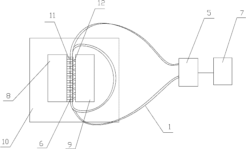
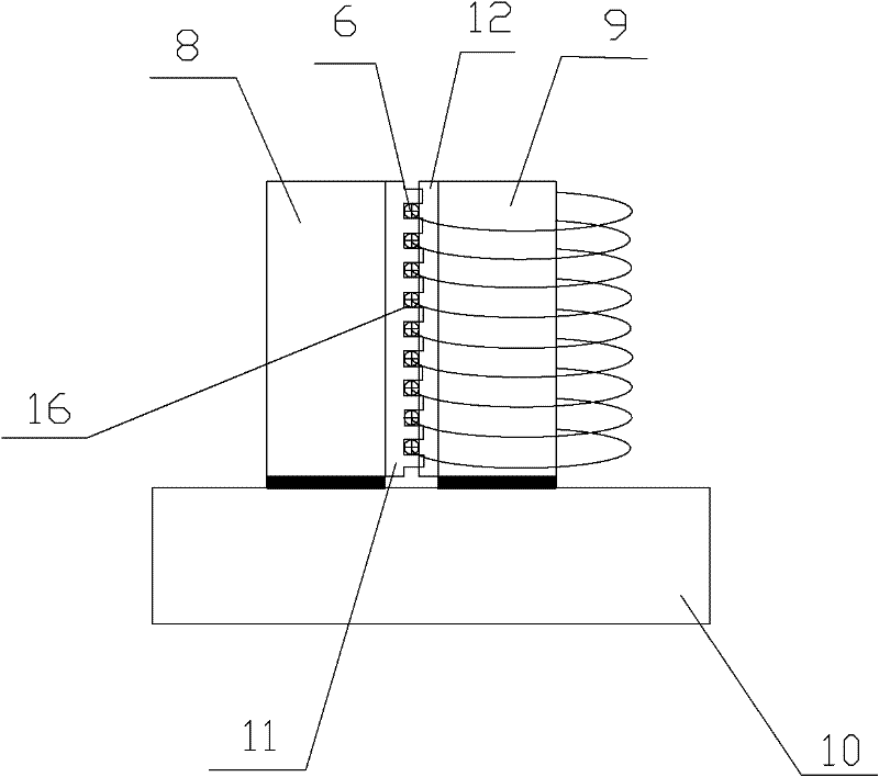
[0035] Such as figure 1 and figure 2 The shown optical fiber sensing device based on optical fiber bending deformation includes a substrate one 10, said substrate one 10, at least one of three or at least one of the first sawtooth plate 8 and the second sawtooth plate 9 arranged on the first substrate 10 A part of one of the three is made of functional materials, the first sawtooth plate 8 is provided with a deformation tooth 11, the second sawtooth plate 9 is provided with a second deformation tooth 12, and the first deformation tooth 11 and the second deformation tooth 12 are staggered and corresponding to each other. The signal optical fiber 6 is arranged on the sawtooth plate 2 9. The signal optical fiber 6 is in the shape of a multi-turn circle and is clamped between the deformation tooth 1 8 and the deformation tooth 2 9. Preferably, the sawtooth plate 2 The first plate 8 or the second sawtooth plate 9 has a groove 16 at an angle with the deformed teeth 18, and the sig...

Embodiment 2

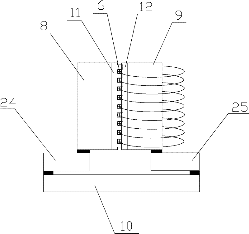
[0041] Such as image 3 As shown, the difference between the present embodiment and the first embodiment is only that the first sawtooth plate 8 and the second sawtooth plate 9 are respectively fixed on the first base plate 10 through the second base plate 24 and the third base plate 25 . The sawtooth plate one 8, sawtooth plate two 9, base plate one 10, base plate two 24, base plate three 25, deformed teeth one 11, deformed teeth two 12 and signal optical fiber 6 satisfy the following formula:

[0042] alpha 1 L 1 ΔT-α 2 L 2 ΔT-α 3 L 3 ΔT-α 齿 (L 1齿 +L 2齿 )ΔT-α 纤 d 纤 ΔT=0

[0043] Among them, α 2 and alpha 3 Respectively, the expansion coefficients of substrate two 24 and substrate three 25 materials, α 1 is the expansion coefficient of substrate-10 material, where L 2 , L 3 are the lengths of the second substrate 24 and the third substrate 25 respectively, ΔT is the changing temperature value, L 1 is the length of substrate one 10, α 齿 is the expansion coeff...

Embodiment 3

[0046] Such as Figure 4 and Figure 5 As shown, the difference between this embodiment and Embodiment 1 is that the first deformed teeth 11 are arranged around the central point of the sawtooth plate 8 to radiate around, and the second deformed teeth 12 are arranged around the center of the sawtooth plate 9 The central point of the center is arranged in a way that the center emits to the surroundings. In this embodiment, the structures, connections and working principles of other parts are the same as those in Embodiment 1.


PUM


Abstract

The invention discloses an optical fiber sensing device based on optical fiber bending deformation. The sensing device is characterized by comprising a baseplate I, wherein at least one of the baseplate I, a fish back I and a fish back II arranged on the baseplate I or at least one part of three is composed of a function material, and the fish back I is provided with a deformation teeth I; the fish back II is provided with a deformation teeth II, the deformation teeth I and the deformation teeth II are corresponding in a staggered manner, the deformation teeth II is provided with a signal optical fiber, and the signal optical fiber is a of multiturn surrounding shape and clamped between the deformation teeth I and the deformation teeth II; and the signal optical fiber is connected with a prolonging optical fiber, the prolonging optical fiber is connected with a testing unit, and the testing unit is connected with a processing unit. The sensing device provided by the invention has the advantages of being capable of carrying out amplification on the collected physical quantity, improving the accuracy of the sensing device combine and prolonging the service life of the signal optical fiber; and the structure is simple, and the sensing device is convenient to use and convenient to popularize and use.

Description

technical field [0001] The invention relates to a detection device, in particular to an optical fiber sensing device based on optical fiber bending deformation. Background technique [0002] At present, the measurement methods used in fiber optic current sensors mainly include the polarization state measurement method of light, the interferometry method of light and the wavelength modulation measurement method. The measurement of the polarization state of light is mainly based on the Faraday magneto-optic effect. The magneto-optic crystal is used to change the polarization direction of light under the external field to achieve the test purpose. It is a relatively mature sensor that has been researched and has been commercialized. Optical interferometry mainly uses the external field to change the optical path difference of coherent light for measurement, mainly based on the measurement of Michelson interferometer or Mach-Zehnder interferometer. Wavelength modulation measure...

Claims


Application Information

Patent Timeline
Patent Type & Authority Applications(China)
IPC IPC(8): G01D5/26G01D5/353G01R19/00G01R15/24G01N21/00
Inventor 杜兵
Owner XIAN JINHE OPTICAL TECH
Why Eureka
Try Eureka