
Glass cracking automatic explosion-proof device

An explosion-proof device and glass technology, which is applied in the direction of automatic disconnection emergency protection device, circuit device, emergency protection circuit device, etc., can solve the problems of fragility hidden dangers, explosion-proof and explosion-proof structure damage, electrical contact sparks, etc.

Inactive Publication Date: 2012-05-16
西安奥能电气有限公司
View PDF5 Cites 2 Cited by
  • Summary
  • Abstract
  • Description
  • Claims
  • Application Information

AI Technical Summary

Problems solved by technology

However, for flammable and explosive environments, the fragility of glass products has great hidden dangers. For example, in order to observe the operation of electrical equipment, transparent glass is often inlaid on the observation window of electrical equipment. , but once the glass breaks, the electrical circuits or components will be exposed to flammable and explosive environments, and the explosion-proof and flameproof structure of the original electrical equipment will be destroyed. Flammable and explosive gas, causing catastrophic consequences

Method used


Image

  • Glass cracking automatic explosion-proof device
  • Glass cracking automatic explosion-proof device
  • Glass cracking automatic explosion-proof device

Examples


Embodiment 1

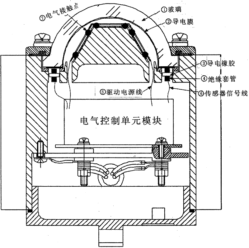
[0022] Example 1. Automatic explosion-proof device for the rupture of the glass lampshade of mine explosion-proof LED roadway lights

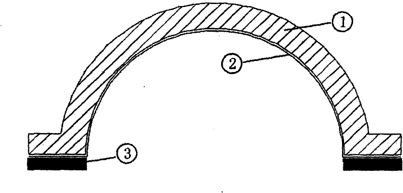
[0023] Figure 2-1 , Figure 2-2 , Figure 2-3 The different positions of the conductive film 2 on the glass lampshade are shown respectively, Figure 2-1 The conductive film 2 is located on the inner surface of the glass lampshade; the metal foil conductive film 2 is attached to the lampshade glass, and the resistance value of the conductive film is 0.001-1MΩ; Figure 2-2 The conductive film is located on the outer surface of the glass lampshade; Figure 2-3 The conductive film is embedded inside the glass.

[0024] image 3 It is a bottom view of the glass cover, and the conductive film 2 is arranged on the glass surface of the lampshade in a cross shape.

[0025] Image 6 Shown is the overall structure of the sensor assembly: when the LED roadway lamp is working normally, the conductive film 2 on the glass lampshade is in a low-resist...

Embodiment 2

[0026] Example 2 The automatic explosion-proof device for the glass breakage of the observation window of the electrical control cabinet

[0027] Figure 4 The flat glass and its conductive film are shown. The flat glass is more likely to be broken by external impact, and the conductive film is attached to the lampshade glass. The resistance value of the conductive film is 0.001Ω~1MΩ.

[0028] like Figure 5 Shown: The glass of the observation window of the electrical control cabinet is flat glass, and the principle of automatic notification of glass breakage of the observation window of the electrical control cabinet is similar to that of underground lighting fixtures used in coal mines. The difference is that the flat glass of the observation window of the electrical control cabinet is more easily broken, its internal space is larger, and the interior is filled with more flammable and explosive gases, which is more harmful.

[0029] Once the glass breaks due to external im...


PUM

PropertyMeasurementUnit
Resistanceaaaaaaaaaa

Abstract

The invention discloses a glass cracking automatic explosion-proof device. A conductive film with lower resistance is arranged on the surface of glass, or a thin conducting wire is embedded into the glass; the conductive film or the thin conducting wire is electrically connected with a circuit board control unit; and the circuit board control unit responds to a change signal and controls a relevant energy supply unit to cut off the supply. The glass cracking automatic explosion-proof device has the advantage that: when the glass is cracked or broken, a sensor acquires relevant information, and remedial measures are taken, so that a disaster is avoided.

Description

Technical field: [0001] The invention relates to an explosion-proof safety device for glass products used in inflammable and explosive environments. Background technique: [0002] Glass products are widely used in various fields, including inflammable and explosive environments, such as glass lampshades for underground lighting lamps in coal mines, due to their incomparable good light transmission, low price, and easy molding. , The glass of the observation window of the electrical control cabinet, etc. However, for flammable and explosive environments, the fragility of glass products has great hidden dangers. For example, in order to observe the operation of electrical equipment, transparent glass is often inlaid on the observation window of electrical equipment. , but once the glass breaks, the electrical circuits or components will be exposed to flammable and explosive environments, and the explosion-proof and flameproof structure of the original electrical equipment wil...

Claims


Application Information

Patent Timeline
IPC IPC(8): H02H5/00
Inventor 李文元
Owner 西安奥能电气有限公司
Learn More