Gas burner for pulverized coal boiler and control method thereof

A technology for gas burners and pulverized coal boilers, which is applied in combustion methods, combustion ignition, lighting and heating equipment, etc., can solve problems such as poor flame stability, high gas consumption, and easy coking during combustion, so as to avoid catastrophic accidents, Simple and reasonable structure and stable ignition efficiency

Active Publication Date: 2014-12-24
NANJING INST OF TECH
View PDF6 Cites 2 Cited by
  • Summary
  • Abstract
  • Description
  • Claims
  • Application Information

AI Technical Summary

Problems solved by technology

The use of natural gas as the ignition fuel can also achieve the purpose of oil-free. The traditional method of starting the ignition of pulverized coal boilers based on natural gas burners is: first use the ignition rod to ignite the gas burner, and then use the burner to ignite the pulverized coal. Natural gas has a high calorific value. Gas, currently the gas consumption of this type of burner is high
Gases with low calorific value, such as blast furnace gas, are by-products of the ironmaking process. They have low calorific value, are easy to coke when burned, and have poor flame stability. However, if they are not utilized, they will cause serious harm to the environment.
In addition, when the gas concentration reaches the explosion limit, it is very easy to cause a huge catastrophic accident.
[0003] Traditional boiler burners have advance and retreat devices, that is, the system needs to send instructions to extend the oil (gas) gun or ignition rod into the designated area during operation. Such telescopic actions require air drives, travel switches, electromagnetic control valves and other pneumatic components and other accessories. Assisted to complete, complex mechanical structure, equipment manufacturing, maintenance, installation, commissioning and other costs are high

Method used


Image

  • Gas burner for pulverized coal boiler and control method thereof
  • Gas burner for pulverized coal boiler and control method thereof
  • Gas burner for pulverized coal boiler and control method thereof

Examples


Embodiment Construction

[0028] The present invention will be further described below in conjunction with the accompanying drawings. The following examples are only used to illustrate the technical solution of the present invention more clearly, but not to limit the protection scope of the present invention.

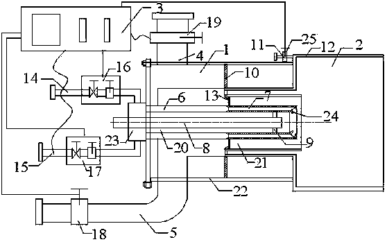
[0029] A pulverized coal boiler gas burner, comprising a burner 1, a primary combustion chamber 2 and a burner control system 3.

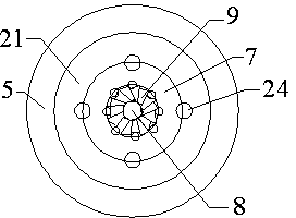
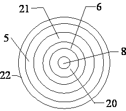
[0030] Such as figure 1 As shown, the burner 1 includes a gas-supporting tube 4 connected to the outer wall 22 of the burner, a hollow tube 8 located in the axial direction of the burner 1, an air passage 20 located outside the hollow tube 8 and connected to the gas-supporting tube 4, and a The mixed gas pipe outside the channel 20 and the pulverized coal air pipe 5 located outside the mixed gas pipe; the front end of the pulverized coal air pipe 5 is connected to the primary combustion chamber 2; the rear end of the burner 1 is provided with a natural gas pipe 14, ...


PUM


Abstract

The invention discloses a gas burner for a pulverized coal boiler and a control method thereof. The gas burner comprises a burner, a first-level combustor and a burner control system and is characterized in that the burner comprises a combustion-supporting gas pipe, a hollow pipe, an air channel, a mixed gas pipe and a pulverized coal air pipe, wherein the hollow pipe is located in the axis direction of the burner; the air channel is communicated with the combustion-supporting gas pipe; the first-level combustor is connected with the front end of the pulverized coal air pipe; a natural gas pipe, a coal gas pipe and a gas mixing cavity are arranged at the rear end of the burner; the gas mixing cavity is connected with the natural gas pipe and the coal gas pipe; the burner control system is electrically connected with a combustion-supporting gas control device, a pulverized coal control device, a natural gas control device, a coal gas control device and a compressed air control device. The gas burner for the pulverized coal boiler has the beneficial effects of simple and reasonable structure, high and stable ignition efficiency, capability of preventing a burning wall from being lagged and eroded, zero oil, gas-saving effect and capability of efficiently avoiding disaster accidents.

Description

technical field [0001] The invention relates to the field of boiler combustion devices, in particular to a pulverized coal boiler gas burner and a control method thereof. Background technique [0002] At present, when the boiler equipment starts to operate or operates at a very low load, a special oil gun is often used to spray heavy oil into the furnace, a high-energy igniter is used to ignite the fuel oil, and then the fuel oil is ignited to ignite the pulverized coal. Since the ignition starts from the cold furnace state, the ignition efficiency of this method is very high. Not high, huge fuel consumption. In order to achieve the purpose of saving fuel or no oil, research and use burners such as micro-oil, less oil, and plasma. The use of natural gas as the ignition fuel can also achieve the purpose of oil-free. The traditional method of starting the ignition of pulverized coal boilers based on natural gas burners is: first use the ignition rod to ignite the gas burner, ...

Claims


Application Information

Patent Timeline
Patent Type & Authority Applications(China)
IPC IPC(8): F23Q9/00
Inventor 叶江明
Owner NANJING INST OF TECH
Why Eureka
Try Eureka