
Residual film recovery device and residual film recovery machine formed by same

A technology of residual film recovery and recycling machine, which is applied in the direction of collectors, agricultural machinery and implements, applications, etc., can solve the problems of difficulty in adapting to residual film recovery operations and complicated mechanisms, and achieve the effect of simple structure and good operation effect

Inactive Publication Date: 2012-05-23
新疆石河子离合器厂
View PDF11 Cites 63 Cited by
  • Summary
  • Abstract
  • Description
  • Claims
  • Application Information

AI Technical Summary

Problems solved by technology

However, there is an obvious deficiency in the pick-up device in the present type of residual film recycling machine: in the operation process, there will always be residual film and plant straws that are difficult to be brushed off by the film brushing mechanism in time and are constantly wrapped around the thorns of the drum. On the nail teeth, the accumulation on the thorn-shaped nail teeth of the drum needs to stop the operation for cleaning before it can work normally
Although the residual film recycling machine disclosed in CN200620114191.5 has improved on this problem, it realizes the extension and contraction of the thorn-shaped nail teeth through the gear and rack mechanism, and the mechanism is relatively complicated, so it is difficult to adapt to the harsh environment of the residual film recycling operation.

Method used


Image

  • Residual film recovery device and residual film recovery machine formed by same
  • Residual film recovery device and residual film recovery machine formed by same
  • Residual film recovery device and residual film recovery machine formed by same

Examples


Embodiment 1

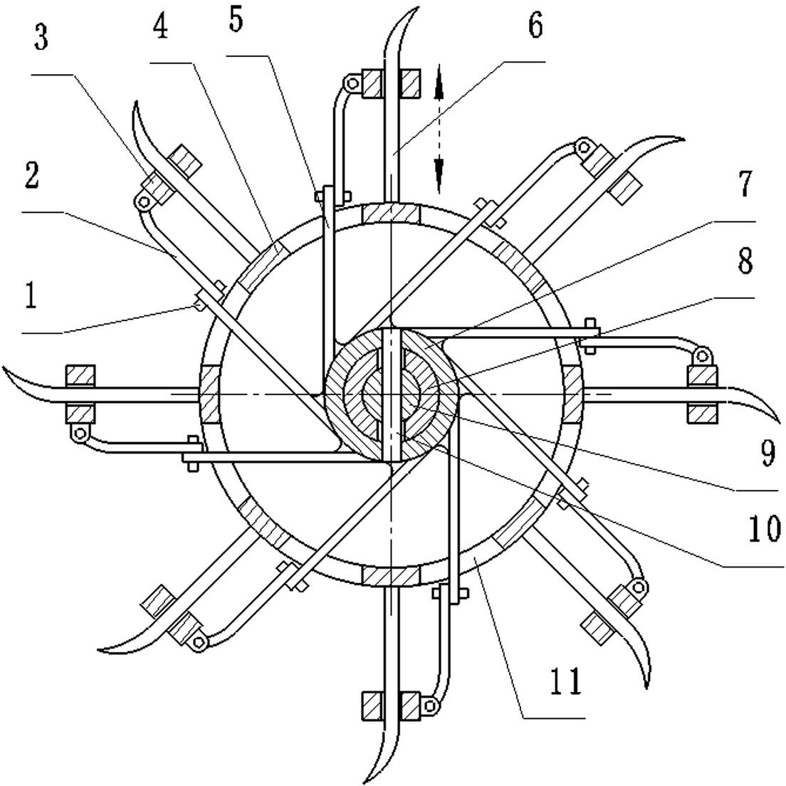
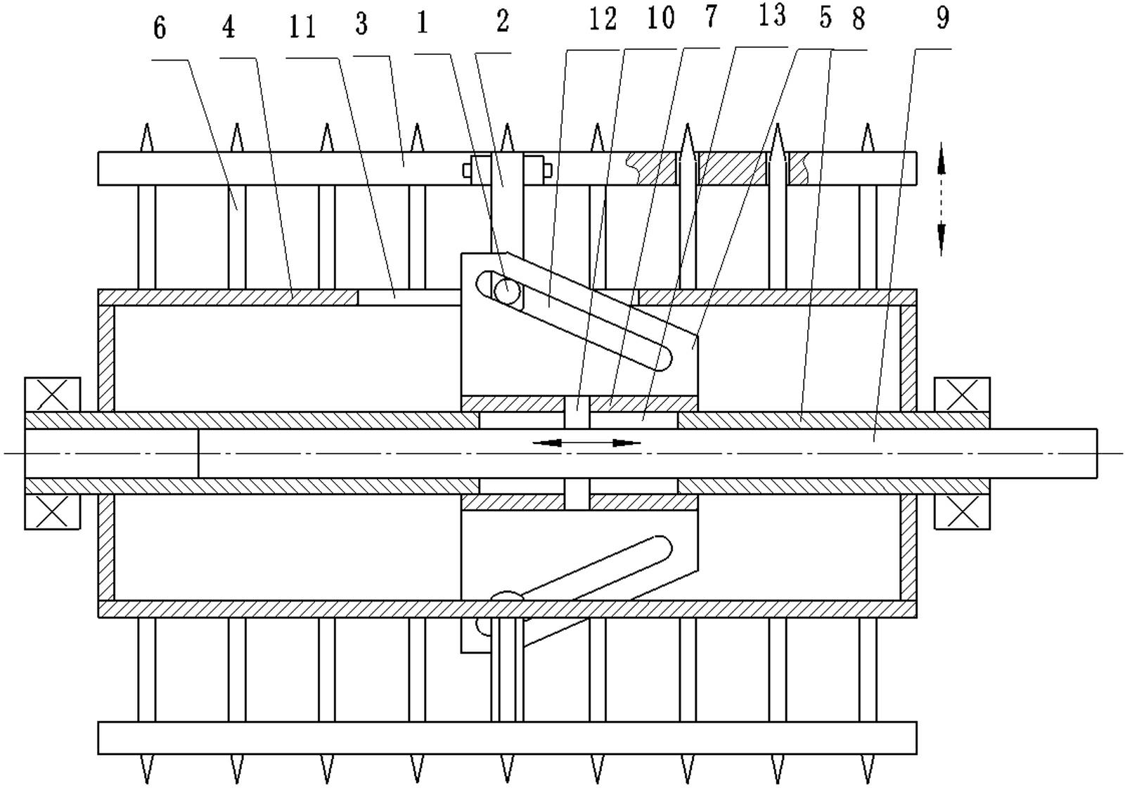
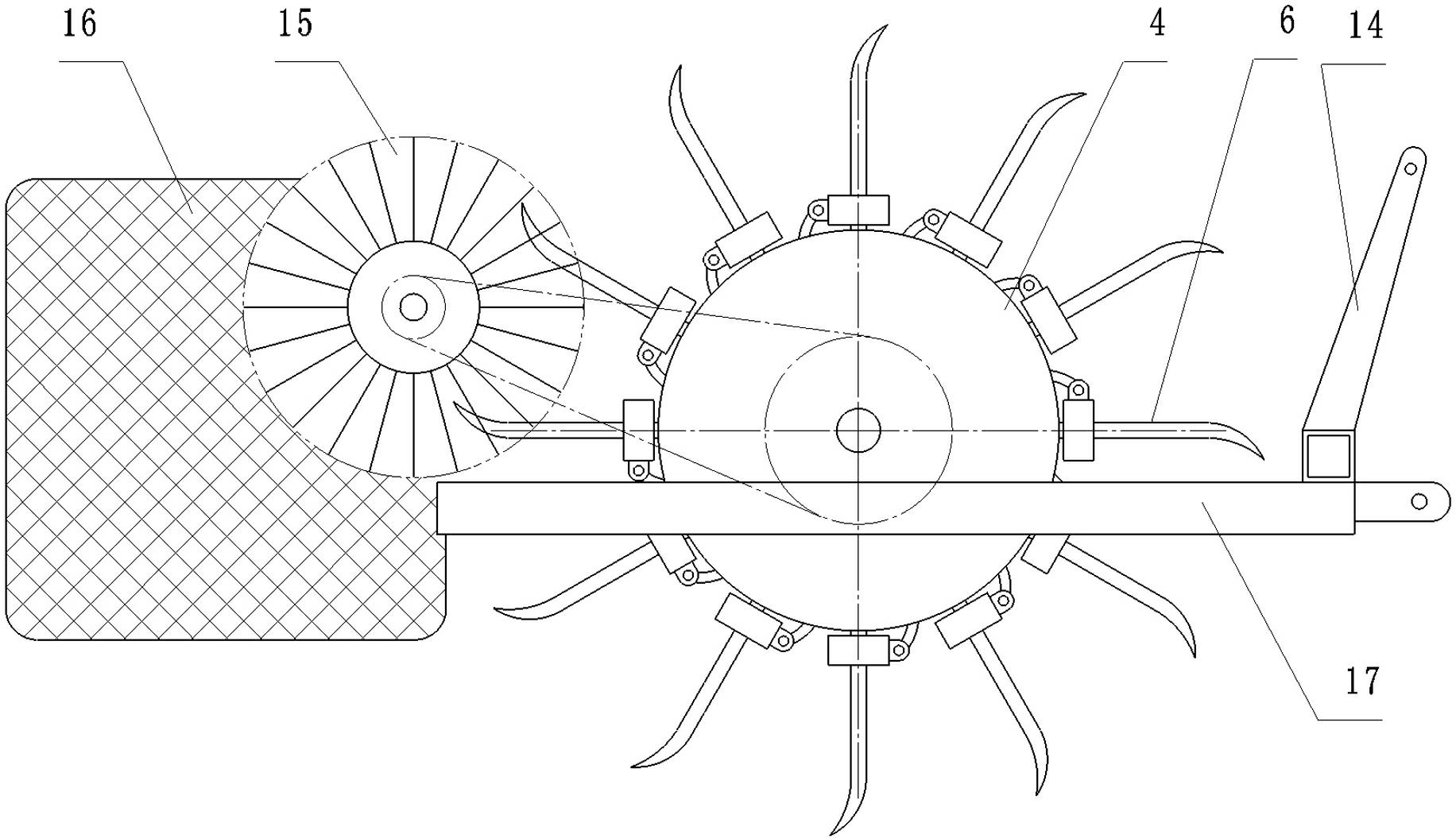
[0023] Embodiment 1: Refer to Figure 1 ~ Figure 3 , is a structural schematic diagram of the residual film recovery device of the present invention applied to a special residual film recovery machine, including a frame 17, a traction suspension frame 14 and a residual film collection box 16, a residual film recovery device is provided on the frame, and a residual film recovery device A film brushing roller 15 is arranged between the residual film collection box 16, and the film brushing roller 15 is a densely clothed elastic bristle cylinder. The residual film recovery device includes a cylindrical hollow cylinder 4, and finger rings are arranged on the outer wall of the cylinder 4. Shaped pick-up teeth 6, the pick-up teeth 6 are axially aligned in a row on the cylinder 4, the pick-up teeth 6 are provided with a film-removing slider 3 that can slide on the tooth body, and the film-removing slider 3 is a strip-shaped plate, Holes matching the cross section of the pick-up teeth...

Embodiment 2

[0024] Embodiment 2: refer to Figure 4 , is an embodiment in which the residual film recovery device of the present invention is applied to a combined land preparation machine. Compared with Example 1, the difference of this embodiment is that the frame 17 at the front of the residual film recovery device is also sequentially provided with round Sheet rake group 18, road wheel 19 and spike-toothed rake 20.

Embodiment 3

[0025] Embodiment 3: refer to Figure 5 , is an embodiment in which the residual film recovery device of the present invention is applied to a combined land preparation machine. Compared with Example 1, the difference of this embodiment is that the frame 17 at the front of the residual film recovery device is also sequentially provided with flat Floor 21, disk harrow group 18 and road wheel 19.


PUM


Abstract

The invention discloses a residual film recovery device and a residual film recovery machine formed by the same. The residual film recovery device comprises a cylindrical hollow roller (4). The periphery of the outer wall of the roller (4) is provided with fingered picking teeth (6). Film withdrawing sliding blocks (3) are arranged on the picking teeth (6). The roller (4) is provided with a hollow shaft (8). A sliding sleeve (7) and chute plates (5) are arranged on the hollow shaft (8). Push-pull connecting rods (2) are arranged between the chute plates (5) and the film withdrawing sliding blocks (3). The residual film recovery device can be applied to various farmland operation machinery to form the residual film recovery machine or a combined land preparation operation machinery. Compared with the prior art, the residual film recovery device and the residual film recovery machine have simple structures and good operation effect; the problem of eliminating wound residual films and plant straws in the operating process is solved; the operation is ensured to be normally carried out; the residual film recovery device can be applied onto various residual film recovery machines and can also be integrated onto other combined land preparation operation machineries or similar operation machineries.

Description

technical field [0001] The invention relates to a residual film recovery device and a residual film recovery machine constituted by the device. Background technique [0002] At present, the application of plastic film planting technology in agricultural production has been very common, which has brought huge benefits to agriculture, but at the same time it has also brought great pollution and harm to the soil and the environment. The soil is hindered by white pollution, which hinders the growth of crops. Severe loss of support ability. Therefore, in the current production, people have fully paid attention to the recycling of the used plastic film, and concentrated recycling through various machines, so that most of the residual film in the production can be recycled, and the phenomenon of large-scale pollution has been suppressed. However, due to years of use, there will always be some mulch film fragments remaining in the soil during the recycling process, which is difficu...

Claims


Application Information

Patent Timeline
IPC IPC(8): A01B43/00
Inventor 陈旺杨靖宇谢映周何建荣周培源王洪晨王江雁
Owner 新疆石河子离合器厂
Learn More