
Surface mount device (SMD) type solid laser, and adjusting device, and manufacturing method for SMD type solid laser

A technology of solid-state lasers and manufacturing methods, which is applied in the direction of semiconductor lasers, lasers, laser parts, etc., can solve the problems of time-consuming and labor-intensive adjustments, reduce errors and inconvenience, reduce matching procedures, and change manual adjustment methods.

Inactive Publication Date: 2012-05-23
PHOEBUS VISION OPTO ELECTRONICS TECH
View PDF4 Cites 4 Cited by
  • Summary
  • Abstract
  • Description
  • Claims
  • Application Information

AI Technical Summary

Problems solved by technology

[0003] Today, solid-state lasers have not yet been mass-produced. The reason is that when assembling solid-state lasers, a single optical element is inserted into the optical path and manually adjusted and positioned one by one. Traditional solid-state lasers use a flat-cavity structure. Because the resonant cavity of this structure is a point resonance, only one point in the concave surface resonates with the plane mirror, so the adjustment is time-consuming and laborious.

Method used


Image

  • Surface mount device (SMD) type solid laser, and adjusting device, and manufacturing method for SMD type solid laser
  • Surface mount device (SMD) type solid laser, and adjusting device, and manufacturing method for SMD type solid laser
  • Surface mount device (SMD) type solid laser, and adjusting device, and manufacturing method for SMD type solid laser

Examples


Embodiment Construction

[0032] The present invention will be described in detail below in conjunction with the accompanying drawings.

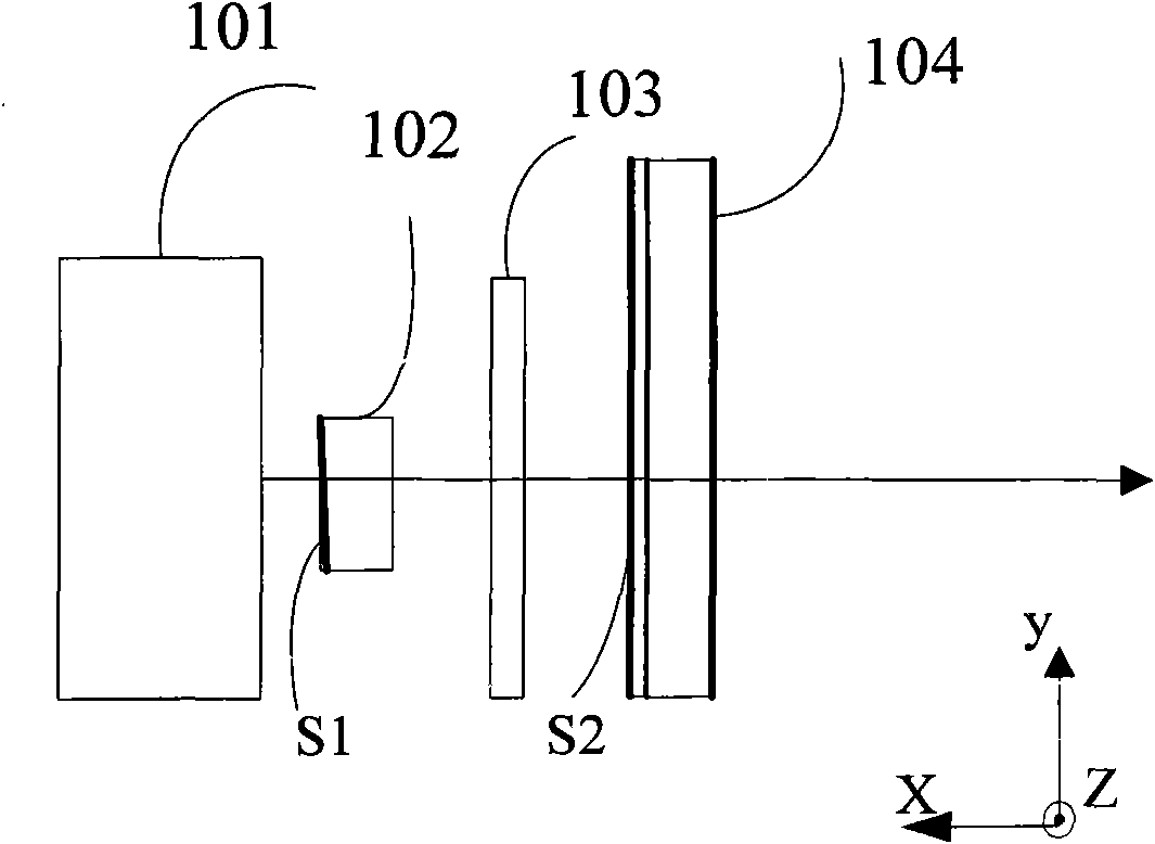
[0033] figure 1 It is a schematic diagram of the component position structure of the patch type solid-state laser described in the present invention.

[0034] Such as figure 1 As shown, the patch type solid-state laser 10 disclosed in the present invention includes an LD pump light source 101 and a resonant cavity, and the resonant cavity is composed of a laser crystal 102 parallel to each other, a frequency doubling crystal 103 and a planar output mirror 104, Wherein, the incident surface S1 of the laser crystal 102 and the incident surface S2 of the planar output mirror 104 form a flat cavity. LD pumping light source 101, laser crystal 102, frequency doubling crystal 103 and planar output mirror 104 are all fixed on the laser substrate with corresponding grooves.

[0035] Wherein, the LD pumping light source 101 is used to provide pumping light.

[0036] The la...


PUM


Abstract

The invention discloses a surface mount device (SMD) type solid laser. The SMD type solid laser comprises a laser diode (LD) pump light source and a resonant cavity, wherein the resonant cavity comprises a laser crystal, a frequency doubling crystal and a plane output mirror which are parallel with one another; and the LD pump light source, the laser crystal, the frequency doubling crystal and the plane output mirror are fixed in the corresponding grooves of a laser substrate sequentially. In addition, the invention also discloses an adjusting device and a manufacturing method for the SMD type solid laser. The SMD type solid laser has a plano-plano cavity structure; the laser substrate serves as a mina supporting body; and the corresponding grooves are formed in the laser substrate, so only the positions of the optical components are adjusted, the optical components can be fixed in the corresponding grooves, and the manufacturing steps are simplified.

Description

technical field [0001] The invention relates to the field of solid-state lasers, in particular to a patch-type solid-state laser. In addition, the invention also discloses an adjustment device and a manufacturing method of a patch type solid-state laser. Background technique [0002] Lasers can be widely used in military, industrial, medical, commercial, scientific research and many other fields. With the advancement of science and technology, the performance requirements of lasers in these application areas are also getting higher and higher, and high stability and good laser quality have become the main requirements. Therefore, more types of lasers emerged as the times require. Among them, a laser diode (Laser Diode, LD for short) pumped solid-state laser is one of them. It not only has the advantages of full curing, high conversion efficiency, good beam quality, low power consumption, light weight, long life, etc. This method works in a wider range of applications. Us...

Claims


Application Information

Patent Timeline
Patent Type & Authority Applications(China)
IPC IPC(8): H01S5/068H01S5/10
Inventor 毕勇张瑛王斌鲍光
Owner PHOEBUS VISION OPTO ELECTRONICS TECH
Learn More