
Compressor

A technology for a compressor and a compression chamber, applied in the field of compressors, can solve the problems of complex structure of rotary compressors, increased assembly man-hours, and increased manufacturing costs, and achieves the effects of reducing load burden, improving reliability, and reducing manufacturing costs.

Active Publication Date: 2014-08-20
DAIKIN IND LTD
View PDF6 Cites 1 Cited by
  • Summary
  • Abstract
  • Description
  • Claims
  • Application Information

AI Technical Summary

Problems solved by technology

Therefore, there are problems in that the structure of the rotary compressor is complicated, and the man-hours for its assembly are increased, and the manufacturing cost is increased.

Method used


Image

  • Compressor
  • Compressor
  • Compressor

Examples


no. 1 Embodiment approach

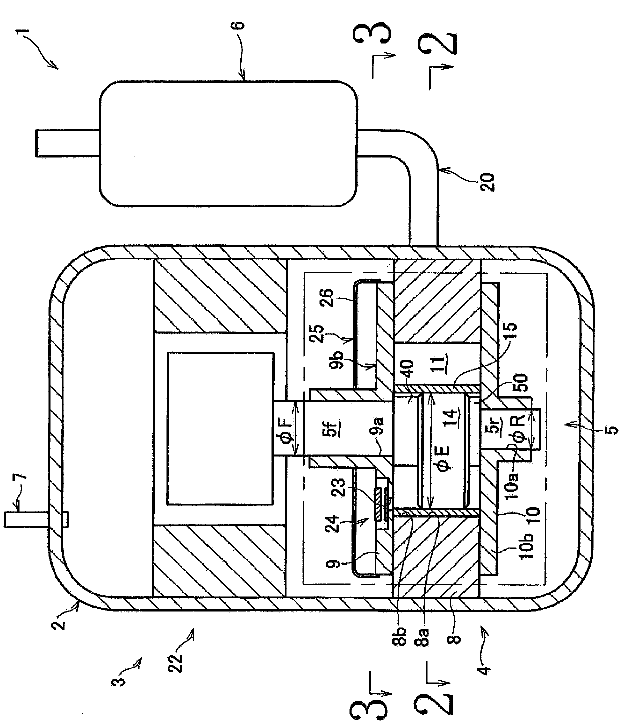
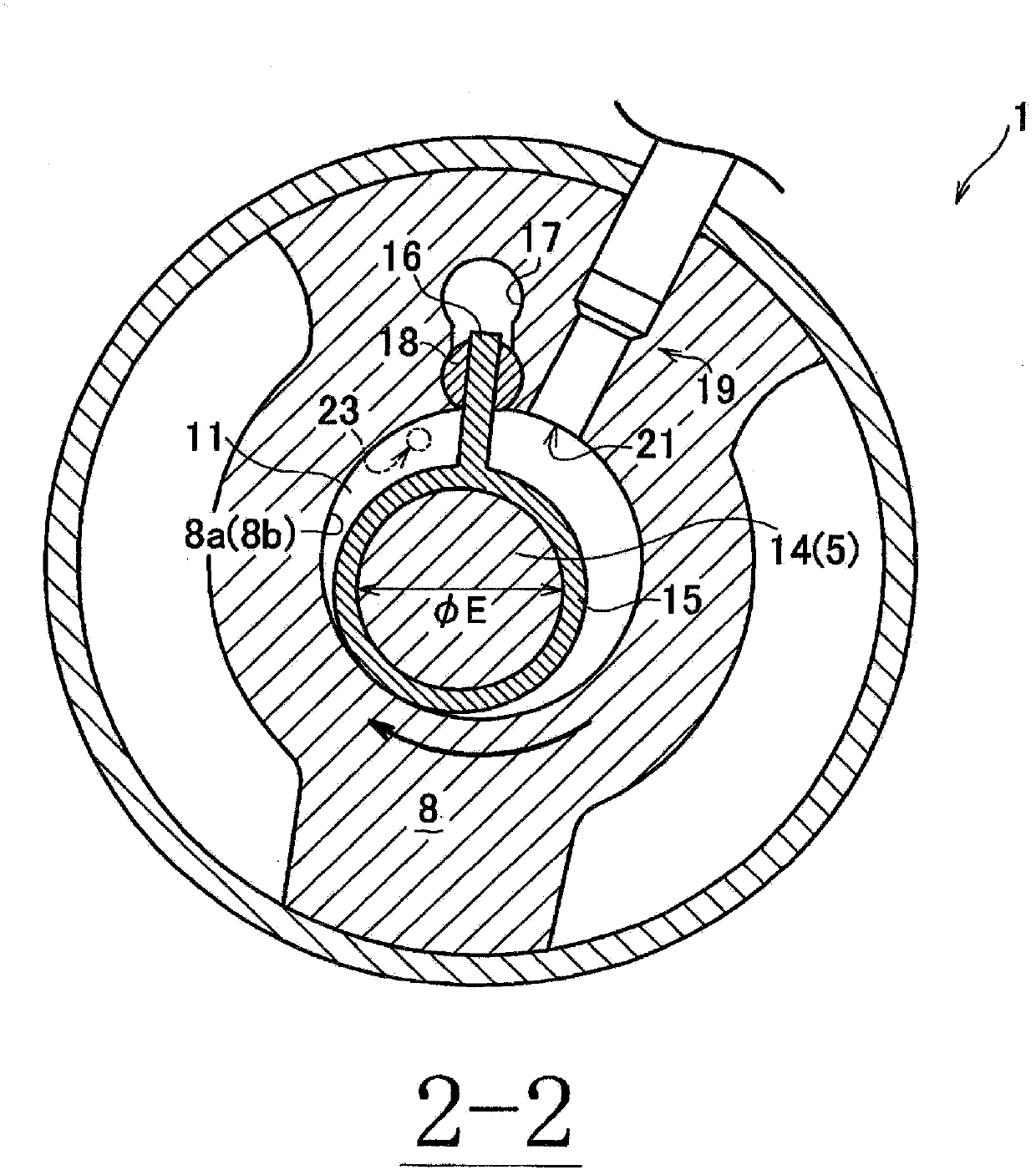
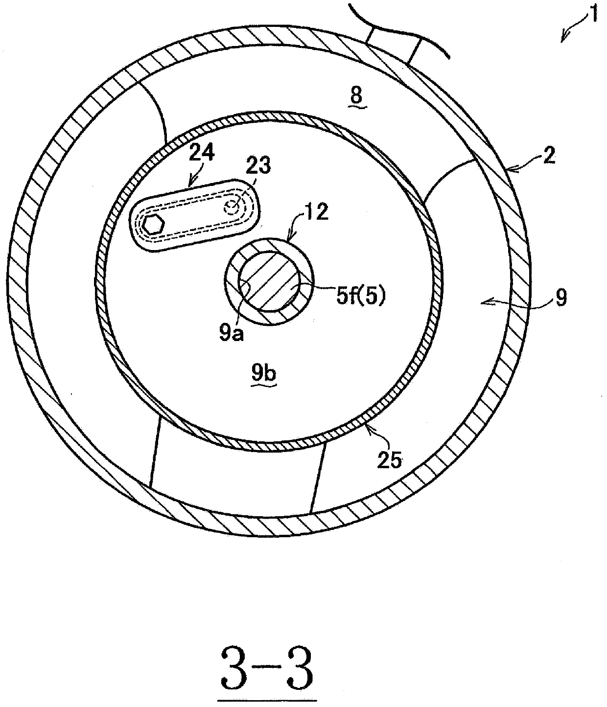
[0038] Next, the configuration of the rotary compressor according to the first embodiment of the present invention will be schematically described. figure 1 It is a vertical cross-sectional view of the rotary compressor according to the first embodiment of the present invention. figure 1The illustrated rotary compressor 1 is used to constitute a part of a refrigeration system such as an air conditioner, for example. That is, the air conditioner mainly includes a condenser, an expansion mechanism, an evaporator, and the above-mentioned rotary compressor 1 , which are not shown in the figure.

[0039] This rotary compressor 1 is constituted as a single-cylinder type rotary compressor for refrigerant, and sucks the CO in the above-mentioned air conditioner. 2 Refrigerant (hereinafter simply referred to as refrigerant), and discharge the refrigerant at a predetermined pressure. As shown in this figure, this rotary compressor 1 is mainly comprised by the airtight container 2, and...

no. 2 Embodiment approach

[0070] Next, a second embodiment of the present invention will be described. Figure 9 It is a vertical sectional view of the rotary compressor of 2nd Embodiment of this invention. Here, the description will focus on the differences from the above-mentioned first embodiment, and the description of overlapping parts will be omitted. The same reference numerals are assigned to components common to the rotary compressor 1 of the first embodiment and the rotary compressor 101 of the second embodiment.

[0071] First, the rotary compressor 1 of the first embodiment is configured as a single-cylinder type rotary compressor for refrigerant, but the rotary compressor 101 of the second embodiment is configured as a two-cylinder type rotary compressor for refrigerant. Furthermore, in the first embodiment, only one cylinder main body 8 was provided, but in this embodiment, two cylinder main bodies 8 are provided in parallel in the axial direction of the crankshaft 5 . Furthermore, an i...


PUM


Abstract

The reliability of a rear shaft is enhanced without using a separate element such as a reinforcing ring. A compressor (1) is provided with a cylinder body (8) having a compression chamber (11); a crank shaft (5) having an eccentric shaft portion (14) housed in the inside of the compression chamber (11), and a first shaft portion (5f) and a second shaft portion (5r) which are arranged on opposite sides of the eccentric shaft portion (14); a first head member (9) which is arranged at one end of the cylinder body (8) and which is capable of supporting the first shaft portion (5f); a second head member (10) which is arranged at the other end of the cylinder body (8) and which is capable of supporting the second shaft portion (5r); and an annular member (15) which is fitted on the eccentric shaft portion (14) in the inside of the compression chamber (11). In a side view, the central position (P1) of the eccentric shaft portion (14) arranged in the inside of the compression chamber (11) in the axial direction is located closer to the second shaft portion (5r) than the central position (P2) of the compression chamber (11) in the axial direction.

Description

technical field [0001] The present invention relates to a compressor used in household appliances and the like. Background technique [0002] As such a technique, there is disclosed a rotary compressor in which a transmission unit is housed in an upper part of an airtight container, a compression unit is housed in a lower part, and the rotational force of the transmission unit is transmitted to the compression unit by a rotating shaft for driving (e.g. Refer to Patent Document 1). The rotating shaft is composed of a front shaft, a pin shaft (eccentric shaft), and a rear shaft. Since the piston is externally fitted on the pin, the outer diameter of the rear axle is set to be smaller than that of the front axle. Therefore, in order to prevent the reliability of the rear shaft from being lowered, in the rotary compressor of Patent Document 1, a reinforcement ring is inserted into and fixed to the rear shaft. [0003] prior art literature [0004] patent documents [0005] ...

Claims


Application Information

Patent Timeline
Patent Type & Authority Patents(China)
IPC IPC(8): F04C18/356F04C18/32
CPCF04C2240/50F01C21/02F04C29/0057F04C18/322F04C28/28F04C29/0085F04C23/02F04C18/3564
Inventor 关口展平
Owner DAIKIN IND LTD
Learn More