
Photoelectric control yarn feeding equipment

A photoelectric control and yarn feeding technology, which is applied in textiles, papermaking, knitting, etc., can solve the problems of complex control circuit of the yarn feeding device, unfavorable mass production, and inability to guarantee the quality of fabrics, etc., so that the detection results are intuitive and easy to implement , to ensure the effect of accuracy

Inactive Publication Date: 2012-05-30
DALIAN ZHAOYANG SOFTWARE TECH
View PDF1 Cites 0 Cited by
  • Summary
  • Abstract
  • Description
  • Claims
  • Application Information

AI Technical Summary

Problems solved by technology

Artificially checking whether there is yarn on the surface of the yarn storage device of the yarn feeding device will greatly increase the production cost, which is very laborious, and once a large number of yarn feeding devices are managed at the same time, the probability of errors will increase, and then it cannot be guaranteed. Therefore, with the rapid development of industrial automation, manual detection has been gradually replaced by intelligent automatic detection devices
[0003] At present, there are already many yarn delivery devices that can automatically judge whether there is yarn in the yarn storage area on the surface of the yarn storage device, such as the Chinese utility model patent "A Kind of Yarn with Photoelectric Detection Function" with the patent number ZL200520012996.4 (the announcement number is CN2808954Y). Yarn Delivery Device", which discloses a yarn delivery device using a photoelectric detection method, which includes a motor controlled by a control circuit, a yarn storage device driven by the motor, and a detector connected to the control circuit, wherein the yarn storage The detector is surrounded by a plurality of grids arranged vertically, and the detector faces the scanning area provided on the surface of the yarn storage device. The yarn delivery device obtains the target output signal by comparing the detection signals obtained by the plurality of detectors respectively. According to the value of the target output signal, it is judged whether there is yarn in the scanning area provided by the surface of the yarn storage device. Therefore, the control circuit using this photoelectric detection method needs to include at least a differential amplifier and a central processing unit that can control the drive motor to stop. circuit, which makes the control circuit of the yarn feeding device more complicated, which will increase the production cost and is not conducive to mass production

Method used


Image

  • Photoelectric control yarn feeding equipment
  • Photoelectric control yarn feeding equipment
  • Photoelectric control yarn feeding equipment

Examples


Embodiment Construction

[0012] The present invention will be further described in detail below in conjunction with the accompanying drawings and embodiments.

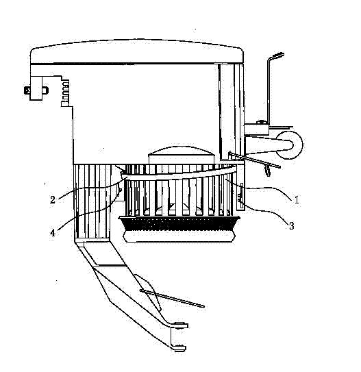
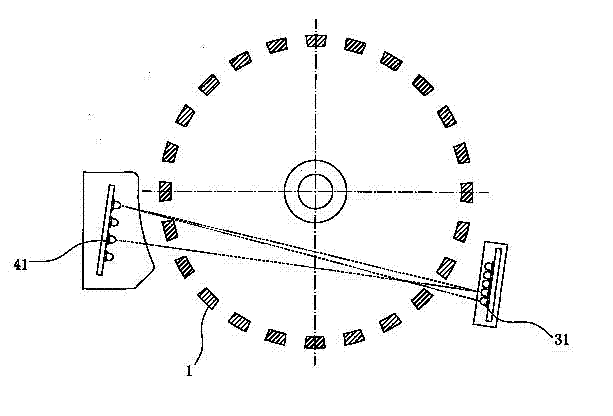
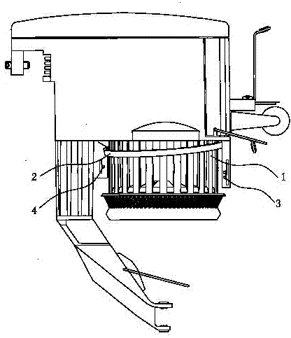
[0013] Such as Figure 1 ~ Figure 2 As shown, the yarn feeding device with photoelectric detection function includes a motor (not shown in the figure) controlled by a control circuit, a yarn storage device 1 driven by the motor, and a yarn pressing ring 2 arranged on the upper part of the yarn storage device 1 A detector composed of a pair of transmitting device 3 and receiving device 4;

[0014] Wherein, the transmitting device 3 is arranged on one side of the yarn storage device 1, and faces the scanning area provided on the surface of the yarn storage device 1, and the receiving device 4 is arranged relative to the transmitting device 3 and is located at the side of the yarn storage device 1. On the other side, the transmitter 3 is controlled by the control circuit to start its work, and the output terminal of the receiver 4 is...


PUM


Abstract

The invention relates to photoelectric control yarn feeding equipment, which comprises a motor controlled by a control circuit, a detector and a yarn storage device driven by the motor, wherein the detector comprises a pair of transmitting device and receiving device, wherein the transmitting device is arranged at one side of the yarn storage device and faces to a scanning area provided by the surface of the yarn storage device; and the receiving device is arranged opposite to the transmitting device and is positioned at the other side of the yarn storage device. Compared with the prior art, the photoelectric control yarn feeding equipment has the beneficial effects that through the matched detection of the transmitting device and the receiving device, if yarns exist on the yarn storage device, the receiving device can not receive a signal, if yarns do not exist on the yarn storage device, the receiving device can receive the signal; the detection method is very direct and simple; the detection results are direct and clear; the control circuit connected with the receiving device can control the motor to rotate and stop only through knowing whether a signal exists at the output end of the receiving device or not; and the control circuit becomes very simple and facilitates production and manufacturing.

Description

technical field [0001] The invention relates to the technical field of yarn feeding devices in knitting machines, in particular to a photoelectrically controlled yarn feeding device. Background technique [0002] The yarn feeding device is an important part in the knitting machine, which mainly includes a motor-driven yarn storage device. In recent years, with the rapid development and widespread application of large circular knitting machines, whether the yarn feeding device can always ensure that there is yarn in the yarn storage area on the surface of the yarn storage device during the rapid operation process, or prompt the yarn storage device in time Whether there is no yarn in the yarn storage area on the surface, so as to feed yarn automatically or manually in time, is one of the important factors that determine the quality of the fabric woven by the circular knitting machine. Artificially checking whether there is yarn on the surface of the yarn storage device of the...

Claims


Application Information

Patent Timeline
Patent Type & Authority Applications(China)
IPC IPC(8): D04B35/12
Inventor 栾晓健
Owner DALIAN ZHAOYANG SOFTWARE TECH
Learn More