
Improved centrifugal type wind wheel as well as volute and turbine fan assembly

A centrifugal, wind wheel technology, applied in the components, pump components, mechanical equipment, etc. of the pumping device for elastic fluid, can solve the problems of low efficiency, high noise, small air volume, etc., and achieve high noise and low load. , the effect of smooth wind

Inactive Publication Date: 2012-05-30
SINGFUN ELECTRIC GROUP
View PDF6 Cites 8 Cited by
  • Summary
  • Abstract
  • Description
  • Claims
  • Application Information

AI Technical Summary

Problems solved by technology

The defects of the existing centrifugal wind wheel are: the whole wind wheel is relatively tough when cutting the wind, the noise is large, the energy consumption is high, the air volume is small, and the cost is high
[0008] Due to the above-mentioned problems of the wind wheel and the volute, the turbo fan assembly including the wind wheel and the volute also has the above-mentioned problems of high noise, high energy consumption, and low efficiency

Method used


Image

  • Improved centrifugal type wind wheel as well as volute and turbine fan assembly
  • Improved centrifugal type wind wheel as well as volute and turbine fan assembly
  • Improved centrifugal type wind wheel as well as volute and turbine fan assembly

Examples


Embodiment Construction

[0034] Below in conjunction with accompanying drawing, the present invention is described in further detail:

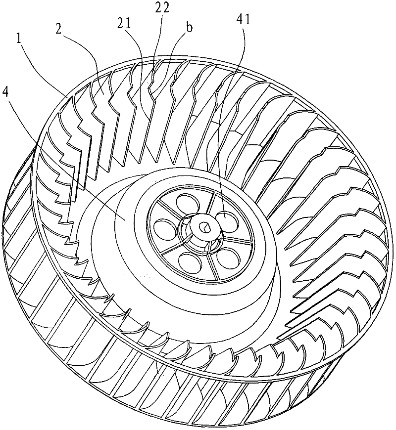
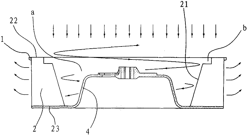
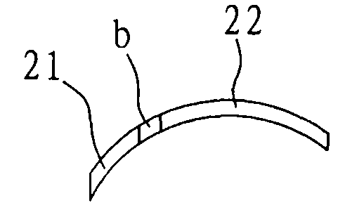
[0035] Such as Figure 1 to Figure 5 As shown, an improved centrifugal wind wheel provided by the present invention includes a base plate 4, blades 2 and stirrups 1, the blades 2 are multiple and distributed on the base plate 4 at intervals, and the stirrups 1 Connect the plurality of blades 2, the plurality of blades 2 and the bottom plate 4 form a negative pressure zone a, the front projection shape of the blades 2 is a right-angled trapezoid, and its hypotenuse 21 faces the negative pressure zone a, the The width of the top edge 22 of the blade 2 is smaller than the width of the bottom edge 23 , and the connecting portion between the hypotenuse 21 and the top edge 22 of the blade 2 is provided with a notch b. Right-angled trapezoid means that one side is a right-angled side, and the other side is a hypotenuse 21, the angle between the hypotenuse 21 and the base 23 i...


PUM


Abstract

The invention relates to an improved centrifugal type wind wheel as well as a volute and a turbine fan assembly. The wind wheel comprises a bottom plate, multiple blades and a stirrup, wherein the multiple blades are distributed on the bottom plate at intervals, the stirrup is connected with the multiple blades, and the multiple blades and the bottom plate form a negative pressure region; the envisaging projection shape of each blade is a right angle trapezoid, the sloping side of each blade faces to the negative pressure region, the width of the top side of each blade is less than that of the bottom side of each blade, and the connecting part of the top side and the sloping side of each blade is provided with a half-baked groove; the centrifuge wind wheel provided by the invention has the characteristics of large air quantity, small noises, low cost, high energy efficiency and the like as compared with the centrifuge wind wheel in the same specification; and the volute is provided with an edgefold stretching into the half-baked groove of the wind wheel, the volute and the edgefold are connected in a match manner so as to be capable of effectively preventing gas from flowing back to an air inlet, and increase the inlet air area effectively, and meanwhile, the air pressure generated by the wind wheel is prevented from counteraction on the incoming air from the air inlet so as to counteract part of air input. If a motor is same, the diameter and height of the wind wheel and the torsion angle of the blades are same, and an air duct system is same, the air quantity of the centrifugal type wind wheel provided by the invention can be improved by more than 20%.

Description

technical field [0001] The invention relates to a centrifugal fan, in particular to an improved centrifugal wind wheel. In addition, the present invention also provides a volute for accommodating the wind wheel. Background technique [0002] At present, the existing centrifugal wind rotor is formed by injection molding of the bottom plate, the blade and the frame at one time, and the shape of the front view projection surface of the blade is a simple rectangle. The defects of the existing centrifugal wind wheel are: the whole wind wheel is tough when cutting the wind, the noise is large, the energy consumption is high, the air volume is small, and the cost is high. [0003] As announced by the State Intellectual Property Office on October 28, 2009, an invention patent named "a centrifugal wind wheel" with a patent number of ZL200920112083.8 discloses a centrifugal wind wheel for a centrifugal fan. The bottom plate, the blades and the frame are injection molded at one time,...

Claims


Application Information

Patent Timeline
Patent Type & Authority Applications(China)
IPC IPC(8): F04D29/28F04D29/30
Inventor 姚国宁刘光辉刘丰恺
Owner SINGFUN ELECTRIC GROUP
Learn More