Charge pump circuit

A charge pump and circuit technology, applied in the direction of conversion equipment without intermediate conversion to AC, can solve the problems of large capacitance and increase in the area and volume of the circuit board of the charge pump circuit, and achieve the effect of reducing the area and volume

Active Publication Date: 2012-05-30
SHANGHAI TIANMA MICRO ELECTRONICS CO LTD
View PDF2 Cites 7 Cited by
  • Summary
  • Abstract
  • Description
  • Claims
  • Application Information

AI Technical Summary

Problems solved by technology

[0003] Since the volume of the capacitor itself is relatively large, too many capa

Method used


Image

  • Charge pump circuit
  • Charge pump circuit
  • Charge pump circuit

Examples


Embodiment Construction

[0045] In order to make the above objects, features and advantages of the present invention more comprehensible, specific implementations of the present invention will be described in detail below in conjunction with the accompanying drawings.

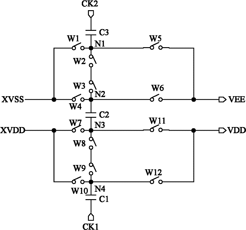
[0046] see figure 1 , which is a structural diagram of the charge pump circuit provided by the present invention.

[0047] The charge pump circuit provided in this embodiment includes: twelve switches, three capacitors, a first clock signal CK1 and a second clock signal CK2;

[0048] The first switch W1 is connected between the first node N1 and the first input terminal XVSS;

[0049] The second switch W2 and the third switch W3 are connected in series between the first node N1 and the second node N2;

[0050] The fourth switch W4 is connected between the second node N2 and the first input terminal XVSS;

[0051] The fifth switch W5 is connected between the first node N1 and the first output terminal VEE;

[0052] The sixth switch ...


PUM


Abstract

The invention provides a charge pump circuit, which comprises twelve switches, three capacitors, six switch signals, a first clock signal and a second clock signal, wherein the six switch signals are used for controlling the twelve switches to be closed and broken off; the charge pump circuit comprises two input ends, namely a first input end and a second input end; the first clock signal and the second clock signal are respectively connected with the first capacitor and the second capacitor; according to the charge conservation principle of the capacitor and the charge pump circuit, the input voltage of the first input end and the input voltage of the second input end are respectively multiplied, the voltage of the first input end is reduced and then is output from the first output end and the voltage of the second input end is boosted and is then output from the second output end; and the voltage rise and voltage reduction are simultaneously realized by only using three capacitors. Therefore, according to the charge pump circuit, the area and the volume of a circuit board can be reduced.

Description

technical field [0001] The invention relates to the technical field of voltage conversion, in particular to a charge pump circuit. Background technique [0002] Charge pumps, also known as switched capacitor voltage converters, are a type of DC-DC converter. They can step up or down the input voltage and can also be used to generate negative voltages. The current charge pump circuit includes a boost charge pump and a buck charge pump. The boost charge pump and the buck charge pump are designed separately, and usually no matter what kind of charge pump circuit, each charge pump circuit requires two or two or more capacitors. [0003] Since the volume of the capacitor itself is relatively large, too many capacitors will increase the area and volume of the circuit board of the charge pump circuit. Contents of the invention [0004] The technical problem to be solved by the present invention is to provide a charge pump circuit, which can be used as both a boost charge pump a...

Claims


Application Information

Patent Timeline
IPC IPC(8): H02M3/07
Inventor 钱栋
Owner SHANGHAI TIANMA MICRO ELECTRONICS CO LTD
Why Eureka
Try Eureka