
Power device

A power plant and power technology, applied in power plant, transmission, pneumatic power plant, etc., can solve the problems of reducing the degree of freedom of the first rotary machine, increasing the size of the power plant, increasing the manufacturing cost, and reducing the degree of freedom of the power plant.

Inactive Publication Date: 2012-05-30
HONDA MOTOR CO LTD
View PDF7 Cites 5 Cited by
  • Summary
  • Abstract
  • Description
  • Claims
  • Application Information

AI Technical Summary

Problems solved by technology

As a result, it inevitably leads to an increase in size and manufacturing cost of the first rotary machine, which in turn leads to an increase in size and manufacturing cost of the power unit.
In addition, in the first rotary machine based on this structure, only the difference between the rotational speeds of the first and second rotating magnetic fields and the rotational speed of the second rotor and the difference between the rotational speeds of the second rotor and the rotational speed of the first rotor are the same. The speed relationship is established, so the degree of freedom in the design of the first rotary machine is reduced, and the degree of freedom in the design of the power plant is reduced

Method used


Image

  • Power device
  • Power device
  • Power device

Examples


Embodiment Construction

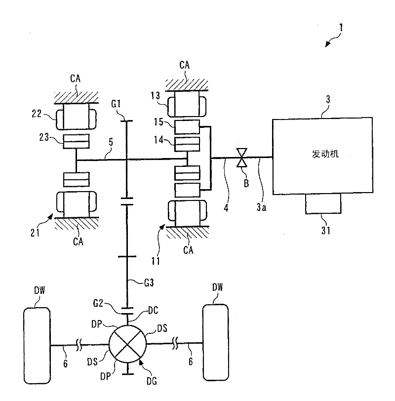
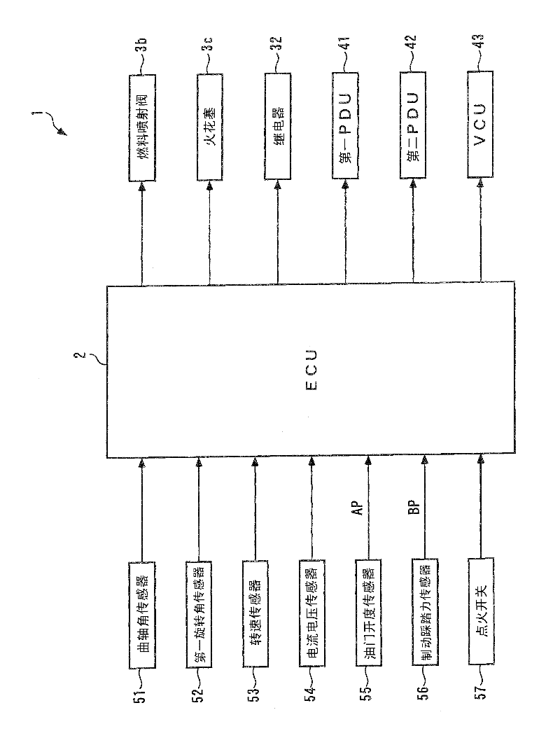
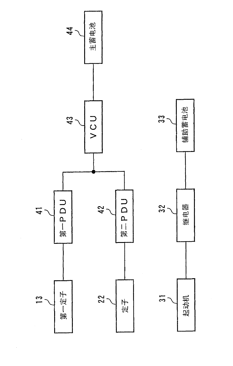
[0243] Hereinafter, preferred embodiments of the present invention will be described in detail with reference to the drawings. figure 1 and figure 2 The shown power plant 1 according to the first embodiment of the present invention is used to drive left and right drive wheels DW, DW of a vehicle (not shown), and includes an internal combustion engine 3 as a power source, a first rotary machine 11, and a second rotary machine. The machine 21, the differential device DG for transmitting power, and the ECU 2 for controlling the operations of the internal combustion engine 3 and the first and second rotary machines 11 and 21 described above. It should be noted that, in figure 1 In other drawings to be described later, hatching of parts showing cross sections is appropriately omitted. In addition, in the following description, the case where each element is directly connected by a shaft etc. without passing through a transmission mechanism, such as a gear, is called "direct co...


PUM


Abstract

Disclosed is a power device in which miniaturization and reduced manufacturing costs can be achieved and in which design freedom can be increased. In the power device (1), a first rotary machine (11) comprises: a first rotor (14) which has a prescribed plurality of magnetic poles (14a); a stator (13) which generates a rotating magnetic field by generating a prescribed plurality of armature magnetic poles; and a second rotor (15) which has a prescribed plurality of soft magnetic bodies (15a). The ratio of the number of armature magnetic poles, the number of magnetic poles, and the number of soft magnetic bodies is set as 1:m:(1+m) / 2(m no equal to 1.0). One of the two rotors (14, 15) is mechanically linked with the output section (3a) of a heat engine (3), while the other of the two rotors (14, 15) and a rotor (23) of a second rotary machine (21) are each mechanically linked with driven sections (DW, DW). Furthermore, the heat engine (3) is started (steps 2, 4) in a state in which the rotational speed of the output section (3a) is not permitted to increase, if the rotational speed of the output section (3a) is equal to or greater than a first prescribed value (NEST1) when the heat engine (3) is started.

Description

technical field [0001] The present invention relates to a power plant including two or more different power sources such as a heat engine and a rotary machine. Background technique [0002] Conventionally, as such a power plant, for example, a power plant disclosed in Patent Document 1 is known. This power unit drives drive wheels of a vehicle, and includes an internal combustion engine as a power source, a first rotary machine, and a second rotary machine. This second rotary machine is of the usual single rotor type. [0003] In addition, the above-mentioned first rotary machine is a double-rotor type, and has a stator, a first rotor, and a second rotor. The first rotor, the second rotor and the stator are arranged sequentially from the inner side along the radial direction. The first rotor has a first permanent magnet row and a second permanent magnet row extending along the circumferential direction and arranged along the axial direction. In addition, the stator is co...

Claims


Application Information

Patent Timeline
IPC IPC(8): B60W10/08B60K6/26B60K6/44B60L11/14B60W10/06B60W20/00F02N11/00F02N11/04H02K16/02B60L50/16
CPCY02T10/6286B60L11/12B60W10/06B60W2510/104Y02T10/48F16H2037/0866Y02T10/641B60L2240/486B60W20/00F02N5/04Y02T10/6243Y02T10/70H02K51/00F02N11/084B60K6/448F02N2200/041Y02T10/7077B60L2220/52B60K6/26F02N2200/022B60W10/08F02N11/04B60L50/15Y02T10/40Y02T10/62Y02T10/64Y02T10/7072
Inventor 圷重光笠冈广太板东真史阿部典行大矢聪义
Owner HONDA MOTOR CO LTD
Learn More