Door suspension apparatus and door apparatus equipped with the same

A door hanger and roller technology, which is applied in the door device, the suspension device of the wing leaf, the application of the lock, etc., can solve the problems of difficulty in adjusting the positions of the locking part and the locked part, and the space of the locking device is small and difficult.

Active Publication Date: 2012-05-30
NABLESCO CORP
View PDF8 Cites 7 Cited by
  • Summary
  • Abstract
  • Description
  • Claims
  • Application Information

AI Technical Summary

Problems solved by technology

However, the space for accommodating the door hanging device and the locking device above the opening is usually quite narrow, so the positions of the locking part and the locked part of the locking device must also be adjusted after the door position adjustment has been completed. Adjusting the homework to become quite difficult homework
In addition, in order to adjust the position of the locking part and the locked part, after adjusting the position of the predetermined member relative to the long hole, the means of tightening the bolt is often used to fix the position, especially in this case, it is easy to cause tightening. The case where the position of the specified member relative to the long hole is shifted when bolting
Therefore, there is a problem that it is very difficult to adjust the position of the locking part and the locked part, and at the same time, a lot of man-hours are required.

Method used


Image

  • Door suspension apparatus and door apparatus equipped with the same
  • Door suspension apparatus and door apparatus equipped with the same
  • Door suspension apparatus and door apparatus equipped with the same

Examples


Embodiment Construction

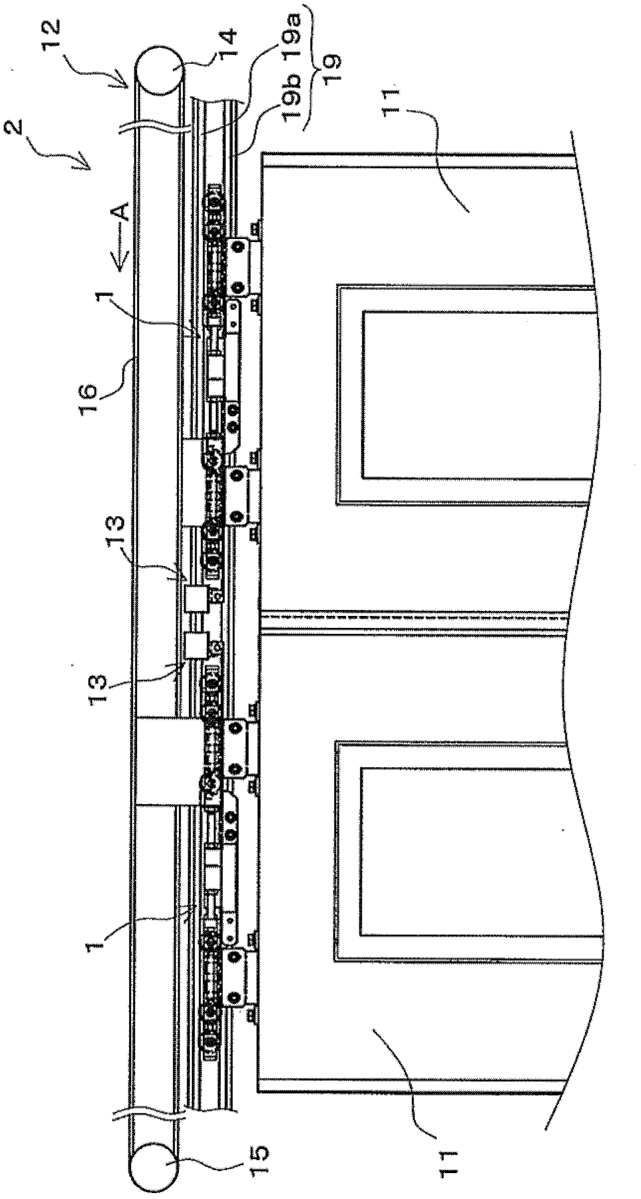
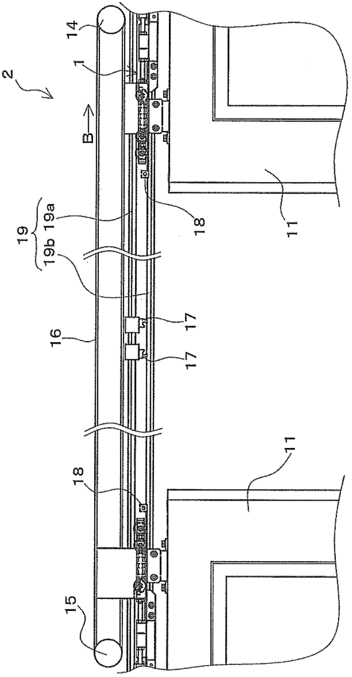
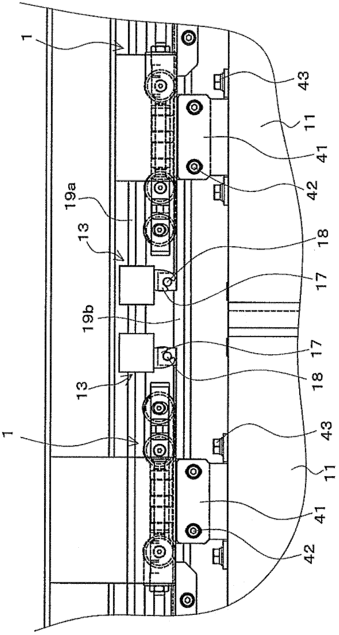
[0062] Hereinafter, modes for implementing the present invention will be described with reference to the drawings. The present invention is applicable as a door hanging device that is installed in a structure and is driven to open and close by a switch drive mechanism, is supported in a state of being slidably suspended relative to the structure, and is connected to the switch drive mechanism, and a door equipped with the door Door device for hanging device. In addition, in this embodiment, a door hanger and a door device applied to a railway vehicle are described as an example, but it is not necessarily limited to this example, and the present invention can be used as a door hanger and a door device installed in various structures. And widely used.

[0063] figure 1 The front view which shows the door apparatus 2 which concerns on one Embodiment of this invention. figure 1 The illustrated door device 2 is suitable, for example, for use as a structure on a side wall of a ra...


PUM


Abstract

Disclosed is a door suspension apparatus that is capable of adjusting the position of a door in the open-close direction thereof without adjusting the positions of a latching part and a part being latched in a locking device. A drive connection unit (21) is provided with one from among the latching part (17) and the part being latched (18) in the locking device (13) that locks the door (11) to a structure in a fully-closed position through the latching of the latching part (17) and the part being latched (18), and is connected to an open-close drive mechanism (12). A door roller unit (22) is connected to the door (11) and provided with door rollers (36a, 36b, 36c) that run on a rail (19) fixed on the structure, and supports the door (11) in a suspended state freely sliding on the rail (19). A variable connection unit (23) connects the drive connection unit (21) and the door roller unit (22) in a manner enabling the alteration of the relative positions of the drive connection unit (21) and the door roller unit (22) in a direction along the lengthwise direction of the rail (19).

Description

technical field [0001] The present invention relates to a door hanging device that supports a door installed on a structure and is driven to open and close by a switch drive mechanism in a state of being slidably suspended relative to the structure, and is connected to the switch drive mechanism. Door fittings for door hangers. Background technique [0002] At present, there is known a door hanger that is installed in a structure and is driven open and close by a switch drive mechanism in a state of being slidably suspended relative to the structure and is connected to the switch drive mechanism (for example, refer to Patent Documents 1, 2). Patent Document 1 and Patent Document 2 disclose that in a railway vehicle as a structure, a door suspended by a door hanger is opened and closed by a switch drive mechanism connected to the door hanger. In addition, in the door hanging devices disclosed in Patent Document 1 and Patent Document 2, door rollers that move on rails are pr...

Claims


Application Information

Patent Timeline
Patent Type & Authority Applications(China)
IPC IPC(8): E05F15/14B61D19/00E05D15/06E05F11/54
CPCB61D19/02E05Y2900/51E05B77/00E05F15/145E05F15/142E05Y2201/22E05F15/148E05Y2201/64E05B65/0829E05F17/004E05Y2800/205E05Y2201/654E05B83/40E05F15/635E05F15/643E05F15/652
Inventor 高桥一玉川崎贺津二
Owner NABLESCO CORP
Why Eureka
Try Eureka