High-pressure fuel pump

A high-pressure pump and fuel technology, applied in fuel injection pumps, fuel injection devices, liquid fuel engines, etc., to achieve weight saving and manufacturing simplification

Active Publication Date: 2012-05-30
ROBERT BOSCH GMBH
View PDF6 Cites 3 Cited by
  • Summary
  • Abstract
  • Description
  • Claims
  • Application Information

AI Technical Summary

Problems solved by technology

[0003] Due to the high delivery pressure there is often a problem in such pumps that large forces act on the drive shaft, precisely forces acting radially and axially with respect to the longitudinal axis of the drive shaft, which must be supplied by the drive shaft bearing unit to receive

Method used


Image

  • High-pressure fuel pump
  • High-pressure fuel pump
  • High-pressure fuel pump

Examples


Embodiment Construction

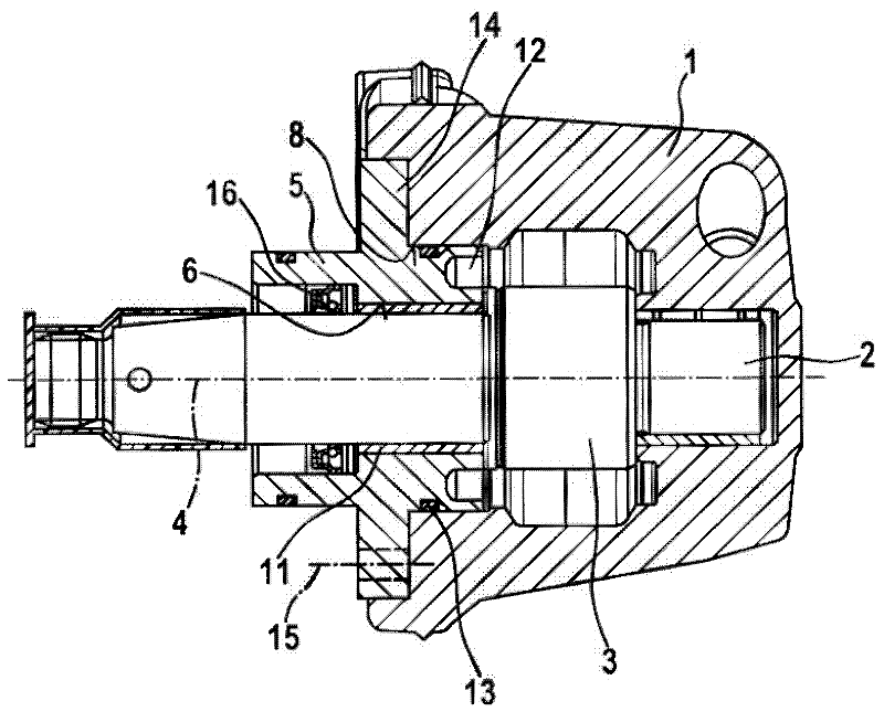
[0021] figure 1 The high-pressure pump shown in and known from the prior art comprises a pump housing 1 in which a formed flange is accommodated for receiving and supporting the drive shaft 2 rotatably about its longitudinal axis 4 Housing part 5 in the form of a disc. In order to form the plain bearing, a plain bearing bushing is inserted in the bearing bore 6 of the housing part 5 . The drive shaft 2 is guided through the plain bearing bushing 11 and its end side is held in the pump housing 1 in a bearing arrangement which is formed as a further plain bearing. The drive shaft 2 has a cam drive 3 for actuating a pump piston (also not shown) of at least one pump element (not shown) for delivering fuel between two slide bearings.

[0022] The housing part 5 is axially abutted against the pump housing 1 by its flange 14 . For fastening, the flange 14 is connected to the pump housing by means of at least one screw 15 . Usually 4 or 6 screws 15 are provided on the flange 14 at...


PUM


Abstract

The invention relates to a high-pressure fuel pump of an internal combustion engine, comprising a pump housing, in which a drive shaft (2) having a cam or eccentric drive (3) is received and rotatably mounted about a longitudinal drive shaft axis (4) for actuating at least one pump element arranged in the pump housing (1). The pump housing (1) comprises a housing part (5) that has a bearing bore (6) and is connected to the pump housing (1) for receiving and rotatably mounting the drive shaft (2). According to the invention, the housing part (5) is connected to the pump housing (1) by way of a frictional press connection (7), wherein the frictional press connection (7) is formed by the housing part (5) comprising at least one section (a, b) that is radially larger in relation to a recess (8) of the pump housing (1) into which the housing part (5) is inserted.

Description

technical field [0001] The invention relates to a high-pressure fuel pump for an internal combustion engine having the features of the preamble of claim 1 . Background technique [0002] Such high-pressure pumps are sufficiently known from the prior art. They are used in particular in motor vehicles to feed fuel, in particular diesel fuel, into a high-pressure accumulator, from where the fuel is injected under high pressure into the combustion chamber of the internal combustion engine. For this purpose, such a high-pressure pump has a drive shaft with a cam or eccentric drive, by means of which at least one pump part is driven into a lifting motion. During the suction stroke of the pump piston, fuel is sucked in from a low-pressure region and during the delivery stroke of the pump piston, the fuel is compressed in the pump working chamber in order to deliver the fuel under high pressure into the high-pressure accumulator. [0003] Due to the high delivery pressure there is...

Claims


Application Information

Patent Timeline
Patent Type & Authority Applications(China)
IPC IPC(8): F02M59/48F04B1/04F04B53/16
CPCF02M59/48F04B1/0404F04B9/042F16C35/02
Inventor A・让特J・阿莱克
Owner ROBERT BOSCH GMBH
Why Eureka
Try Eureka