Cooperative airflow control device

An airflow control device and airflow technology, applied in heating and ventilation control systems, heating methods, lighting and heating equipment, etc., can solve problems such as difficult airflow control, inability to obtain airflow effects, difficult airflow control, etc.

Inactive Publication Date: 2012-05-30
PANASONIC CORP
View PDF3 Cites 7 Cited by
  • Summary
  • Abstract
  • Description
  • Claims
  • Application Information

AI Technical Summary

Problems solved by technology

However, it is difficult to control the air flow accordingly when the indoor environment changes, such as when dust is blown up due to people moving, dust enters due to opening and closing doors, or temperature differences occur
Therefore, the same operation is performed even if the indoor environment changes, so there is a problem that the effect of the airflow can

Method used


Image

  • Cooperative airflow control device
  • Cooperative airflow control device
  • Cooperative airflow control device

Examples


Embodiment approach 1

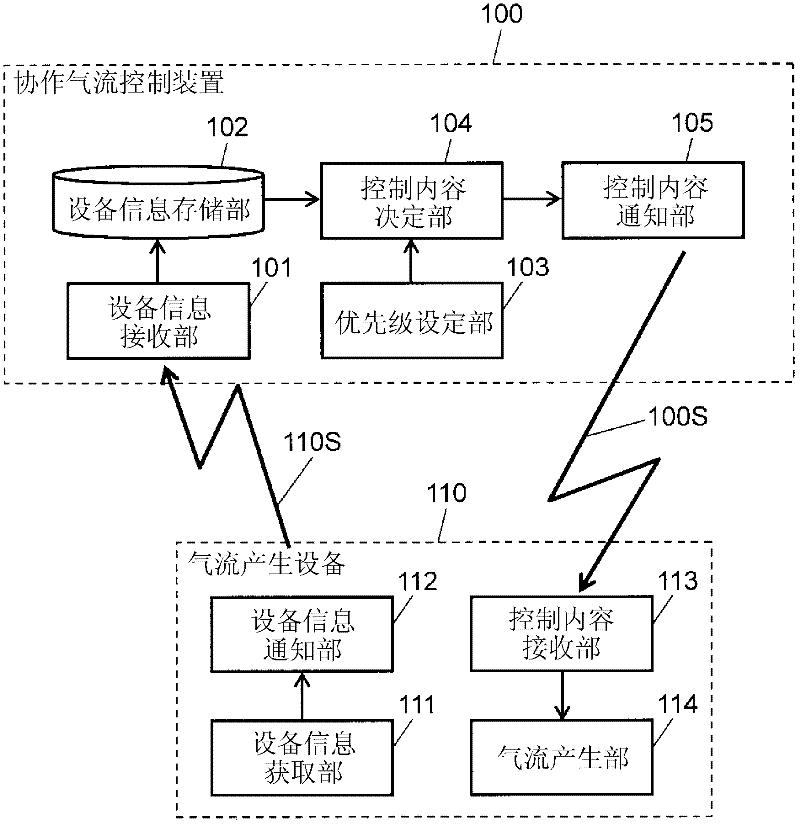
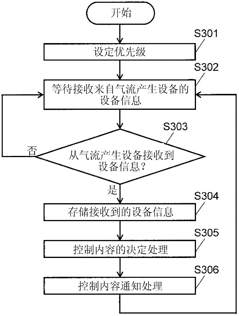
[0028] figure 1 It is a figure which shows the structure of the cooperative airflow control apparatus and airflow generation facility in Embodiment 1 of this invention. figure 2 is a diagram showing cooperation between the cooperative airflow control device and the airflow generating device in this embodiment. image 3 It is a flowchart showing the operation of the cooperative air flow control device in this embodiment.

[0029] exist figure 1 In this embodiment, the cooperative airflow control device 100 in this embodiment cooperates with at least one airflow generating device 110 capable of generating airflow in the room to control the air flow in the room. The airflow generating device 110 is, for example, an air conditioner, an air cleaner, a blower, or other equipment capable of generating airflow indoors. The cooperative airflow control device 100 includes a device information receiving unit 101 , a device information storage unit 102 , a priority setting unit 103 , ...

Embodiment approach 2

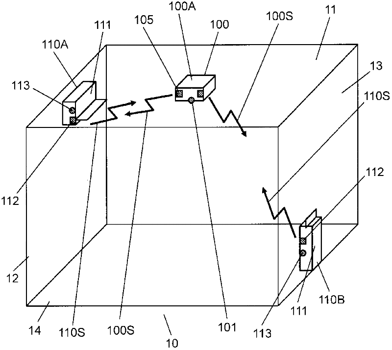
[0063] Figure 4 It is a figure which shows the structure of the cooperative airflow control apparatus and airflow generation facility in Embodiment 2 of this invention. In this embodiment, if Figure 4 As shown, the cooperative air flow control device 100 is installed at the upper central portion of one wall surface 12 constituting the chamber 10 . An air cleaner 110B serving as an airflow generating device 110 is installed in contact with the floor 14 at a lower central portion of a wall surface 13 constituting the chamber 10 facing the wall surface 12 .

[0064] In the present embodiment, the cooperative air flow control device 100 includes the air blower 406 inside. The air blower 406 flows the air in the room 10 similarly to the air flow generating device 110 . The air blower 406 is, for example, a structure that generates air flow such as a fan of an air conditioner, a fan of an air cleaner, a ceiling fan, or a circulator. In addition, as long as the airflow is gener...

Embodiment approach 3

[0069] Figure 5 It is a figure showing the cooperation between the cooperative air flow control device and the air flow generating device in Embodiment 3 of the present invention. In this embodiment, if Figure 5As shown, the cooperative air flow control device 100 is installed at the lower central portion of one wall surface 13 constituting the chamber 10 so as to be in contact with the floor 14 . An air conditioner 110A serving as an airflow generating device 110 is installed at an upper central portion of a wall surface 12 constituting the chamber 10 facing the wall surface 13 .

[0070] In this embodiment, the cooperative air flow control device 100 includes a dust collecting unit 506 . Dust collecting unit 506 has a function of collecting dust floating in room 10 . The dust collecting unit 506 is constituted by, for example, a filter or the like provided in an air cleaner or the like. In addition, the dust collection part 506 of this embodiment may have the electric ...


PUM


Abstract

Disclosed is a cooperative airflow control device provided with a device information storage unit (102) which stores device information (110S) received by a device information receiving unit (101), a priority order setting unit (103) which sets the priority order of at least one airflow generating device (110), a control content determination unit (104) which determines the control content of at least one out of the control content of the device main body and the control content for the airflow generating device (110) on the basis of the device information (110S) and the priority order, and a control content notification unit (105) which transmits the control content determined by the control content determination unit (104) to the airflow generating device (110) in cooperation with the control content determination unit, wherein an airflow is effectively controlled in accordance with the indoor environment or needs of a user, on the basis of the device information (110S) and the priority order.

Description

technical field [0001] The present invention relates to a cooperative air flow control device for controlling air flow in a room in cooperation with at least one air flow generating device in a home. Background technique [0002] As a conventional cooperative air flow control device of this kind, for example, the following technology has been proposed: by combining and using a plurality of air flow generating devices capable of generating air flow indoors, such as an air conditioner, an air cleaner, and a blower, to control the air flow in the entire room to Effectively improve the air-conditioning effect and purification effect. [0003] For example, as shown in Patent Document 1, a cooperative airflow control device has been proposed in which the suction port of the air cleaner faces the arrival position of the blown airflow of the air conditioner, so that the blown airflow of the air cleaner follows the direction of the airflow in the room. The floor and the wall surface...

Claims


Application Information

Patent Timeline
IPC IPC(8): F24F11/04F24F7/007F24F11/02
CPCF24F11/0001
Inventor 黑山和宏江口修福本正美梅景康裕栗原裕明
Owner PANASONIC CORP
Why Eureka
Try Eureka