Pneumatic liquid material conveying device

A conveying device and pneumatic liquid technology, which is applied in the field of pneumatic liquid material conveying devices, can solve the problems of complex equipment structure, low extraction efficiency, waste, etc., and achieve the effects of low manufacturing and use costs, high extraction efficiency, and fast extraction speed

Inactive Publication Date: 2012-06-13
广东山之风环保科技有限公司
View PDF10 Cites 3 Cited by
  • Summary
  • Abstract
  • Description
  • Claims
  • Application Information

AI Technical Summary

Problems solved by technology

[0002] In today's chemical industry, many raw materials or intermediate substances for the production of chemical products are liquid. Due to the large production volume, the liquid materials are generally packed in larger barrels. The following two methods are generally used to take out the materials in the barrel. : 1. Manual dumping. Manual dumping of materials is cumbersome, laborious, and inefficient, and some raw materials are corrosive. If they leak to the outside or the body of the staff, it will cause environmental pollution or personal injury; 2. Use a conventional air pump to extract Liquid, this method has the following disadvantages: 1. The equipment structure is complex, and requires rated power, and the operation is inconvenient; 2. The extraction efficiency is low; 3. The liquid at the bottom of the liquid material barrel cannot be extracted cleanly, causing waste and polluting the environment ; 4. Higher cost; 5. Difficult to clean, etc.

Method used


Image

  • Pneumatic liquid material conveying device
  • Pneumatic liquid material conveying device
  • Pneumatic liquid material conveying device

Examples


Embodiment Construction

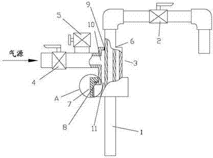
[0013] like figure 1 As shown, the pneumatic liquid material conveying device includes a pump body 3 and a discharge pipe 1. The pump body 3 is a cavity, and an air inlet 10 and an air outlet 11 are arranged on the cavity. The air inlet 10 passes through the pipe The air inlet valve 4 is connected to the pump body, a round hole 6 is arranged on the pump body, and a locking screw cap 7 that can be threadedly connected with the barrel mouth of the liquid material barrel is connected at the air outlet end, and the discharge pipe 1 passes through the pump body The round hole 6 and the locking screw cover 7 on the top, the cavity of the pump body 3 is connected with the cover cavity of the locking screw cover 7, the discharge valve 2 is installed on the discharge pipe 1, and the pump body starts from the inlet valve 4. The air inlet 10, the cavity, the air outlet 11, the cover cavity of the locking screw cap and the inner cavity of the liquid material barrel form a closed and airti...


PUM


Abstract

The invention discloses a pneumatic liquid material conveying device, which comprises a pump body and a discharge pipe. The pump body is a cavity equipped with an air inlet and an air outlet, with the air inlet connected to an air inlet valve through a pipeline, and the pump body is provided with a circular hole. A locking screw cap able to be in threaded connection with the mouth of a liquid material bucket is connected to the air outlet end. The discharge pipe passes through the circular hole on the pump body and the locking screw cap. The cavity of the pump body is communicated with the cap cavity of the locking screw cap. The discharge pipe is provided with a discharge valve. From the air inlet valve and along the air inlet of the pump body, the cavity, the air outlet, the cap cavity of the locking screw cap, as well as the inner cavity of the liquid material bucket, an airtight and sealed airflow channel can be formed. The pneumatic liquid material conveying device of the invention has the advantages of simple structure, easy operation, high extraction efficiency, ability to draw all materials out of a material bucket bottom, low cost, safety and convenience, as well as easy cleaning.

Description

technical field [0001] The invention relates to a pneumatic liquid material conveying device. Background technique [0002] In today's chemical industry, many raw materials or intermediate substances for the production of chemical products are liquid. Due to the large production volume, the liquid materials are generally packed in larger barrels. The following two methods are generally used to take out the materials in the barrel. : 1. Manual dumping. Manual dumping of materials is cumbersome, laborious, and inefficient, and some raw materials are corrosive. If they leak to the outside or the body of the staff, it will cause environmental pollution or personal injury; 2. Use a conventional air pump to extract Liquid, this method has the following disadvantages: 1. The equipment structure is complex, and requires rated power, and the operation is inconvenient; 2. The extraction efficiency is low; 3. The liquid at the bottom of the liquid material barrel cannot be extracted cl...

Claims


Application Information

Patent Timeline
IPC IPC(8): B67C9/00
Inventor 董恩莲
Owner 广东山之风环保科技有限公司
Why Eureka
Try Eureka