Externally-hung sound barrier
A sound barrier and plug-in technology, which is applied in construction, noise absorption devices, etc., can solve the problems of aggravated accidents, unsightly appearance of the sound barrier board, and easy falling off of the sound barrier board, etc., to achieve convenient maintenance and good appearance Beautiful, high safety effect
- Summary
- Abstract
- Description
- Claims
- Application Information
AI Technical Summary
Problems solved by technology
Method used
Image
Examples
Embodiment 1
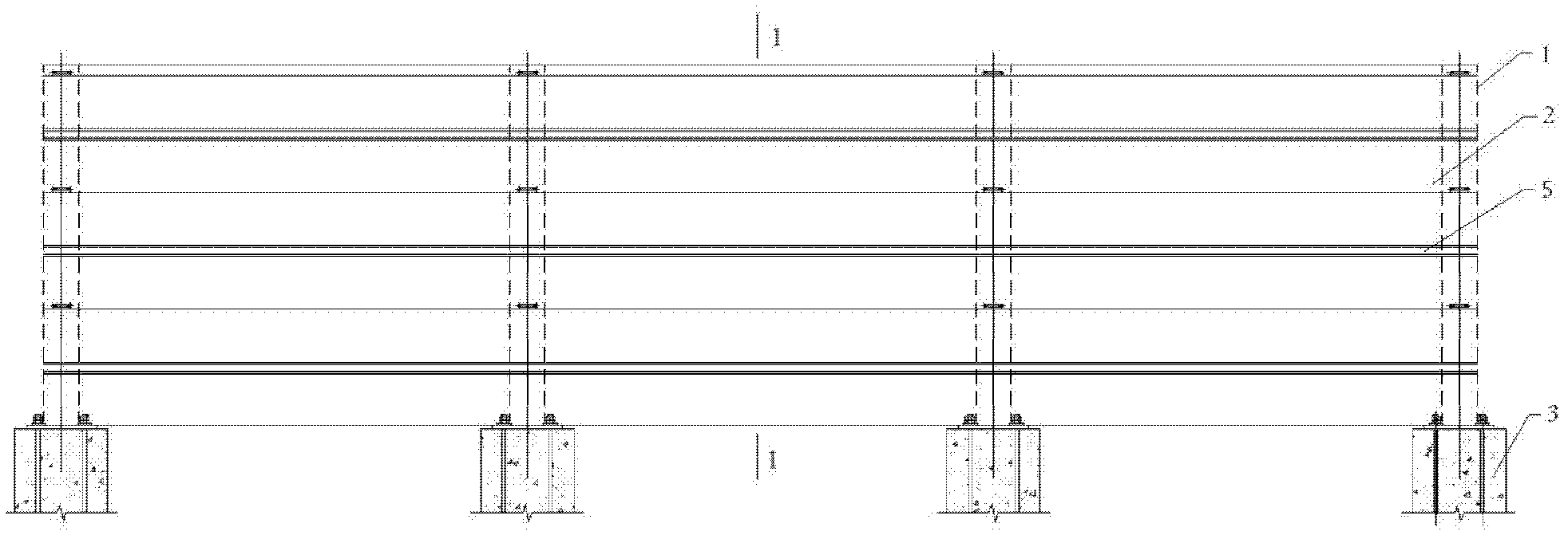
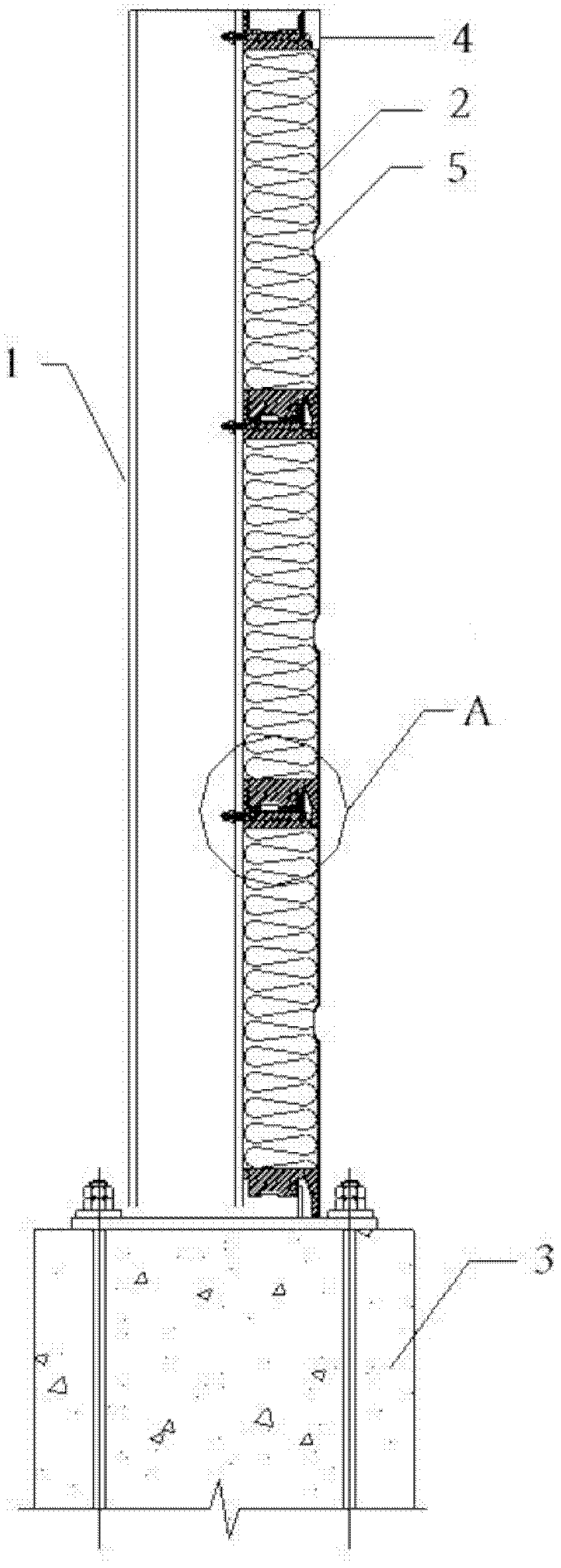
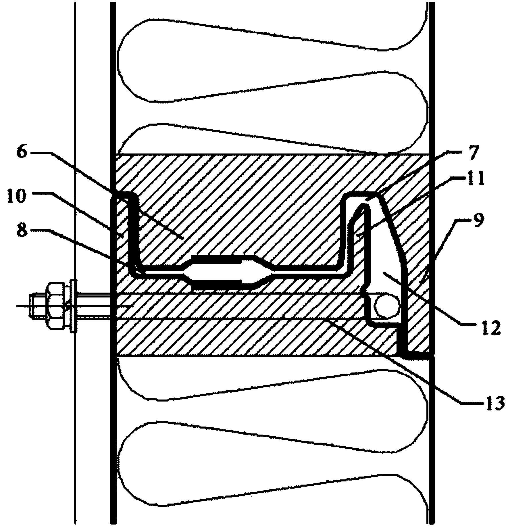
[0030] Such as figure 1 , 2 , 3 and 4, an external sound barrier includes 4 H steel columns 1 and 3 sound barrier unit panels 2 fixedly arranged at intervals along the edge of the roadbed 3, wherein the 4 H steel columns 1 are perpendicular to the roadbed 3 set, and the distance between the adjacent H steel columns is 2m, and the sound barrier unit plate 2 is 6m long and 0.5m wide. The sound barrier unit plate of the present invention is installed on the outer flange of the H steel column 1 facing away from the road, and the length direction of the sound barrier unit plate 2 is perpendicular to the H steel column 1, and spans 4 along the length direction. H steel column 1. The two sides along the length direction of the sound barrier unit plate 2 are formed with groove-and-groove structures that can be plugged into each other. The groove-and-groove structure includes a first groove formed on one side of the sound barrier unit plate and a A second rebate on one side of the f...
Embodiment 2
[0032] Figure 5 It is a top view of the second embodiment of the external-mounted sound barrier of the present invention, four square steel columns 14 and three sound barrier unit panels 2 are fixedly arranged at intervals along the edge of the roadbed, wherein the adjacent square steel columns 14 are The distance is 2m; the sound barrier unit plate is the same as that in Embodiment 1, and its length direction is perpendicular to the square steel column 14, and it spans 4 square steel columns 14 along the length direction. Drill holes at the corresponding positions on the two sides of the square steel column 14 facing the track and back to the track, and the open end of the U-bolt 13 passes through the perforation below the second groove and the two sides of the square column from the side away from the track Correspondingly drill holes, and use nuts to tighten the sound barrier unit plate 2 to fix the outer surface of the square steel column facing away from the track, and i...
Embodiment 3
[0034]Five square steel columns 14 and three sound barrier unit panels 2 are fixedly arranged at intervals along the edge of the roadbed, wherein the distance between adjacent square steel columns 14 is 2m; the length of the sound barrier unit panel 2 is 8m and the width is 0.5m, its structure is the same as that of Embodiment 1, the length direction of the sound barrier unit plate 2 is perpendicular to the square steel column 14, and spans five square steel columns 14 along the length direction. Before installing the external sound barrier, a fixed plate 15 of corresponding size is prefabricated, and drilling holes are set at corresponding positions on the fixed plate 15 . Such as Figure 6 As shown, the open end of the U-shaped bolt 13 passes through the perforation below the second groove draw-in groove from the side away from the track and passes through the borehole on the fixing plate 15 along the two sides of the square steel column, and uses nuts to tighten to make all...
PUM
 Abstract
Description
Claims
Application Information
 - R&D
- Intellectual Property
- Life Sciences
- Materials
- Tech Scout
- Unparalleled Data Quality
- Higher Quality Content
- 60% Fewer Hallucinations
Browse by: Latest US Patents, China's latest patents, Technical Efficacy Thesaurus, Application Domain, Technology Topic, Popular Technical Reports.
© 2025 PatSnap. All rights reserved.Legal|Privacy policy|Modern Slavery Act Transparency Statement|Sitemap|About US| Contact US: help@patsnap.com


