
Drill loader working device

A technology of working devices and drilling rigs, which is applied in the direction of supporting devices, drilling equipment, earthwork drilling and mining, etc., can solve the problems of low overall efficiency, reduced work efficiency, and many auxiliary processes, and achieves a large stroke range, high work efficiency, The effect of accurate hole positioning

Inactive Publication Date: 2014-04-16
JIKAI HEBEI MECHATRONICS TECH CO LTD
View PDF4 Cites 1 Cited by
  • Summary
  • Abstract
  • Description
  • Claims
  • Application Information

AI Technical Summary

Problems solved by technology

When the slag scraper and the rock drilling jumbo are used together, the two equipments need to be used frequently in the wrong way, which is not suitable for narrow sections, the application is limited, the overall efficiency is not high, and the equipment is scattered and there are many auxiliary processes
For the integrated drilling and anchoring machine, there are mainly two working devices, one is the drill arm, which is mainly responsible for drilling holes, and the other is the excavation assembly, which is mainly responsible for discharging gangue. The structure is generally that the two drill arms are respectively arranged at the bottom of the excavation assembly. Both sides, so there is a problem of mutual interference during work, and frequent adjustments are required, which seriously reduces work efficiency

Method used


Image

  • Drill loader working device
  • Drill loader working device
  • Drill loader working device

Examples


Embodiment 1

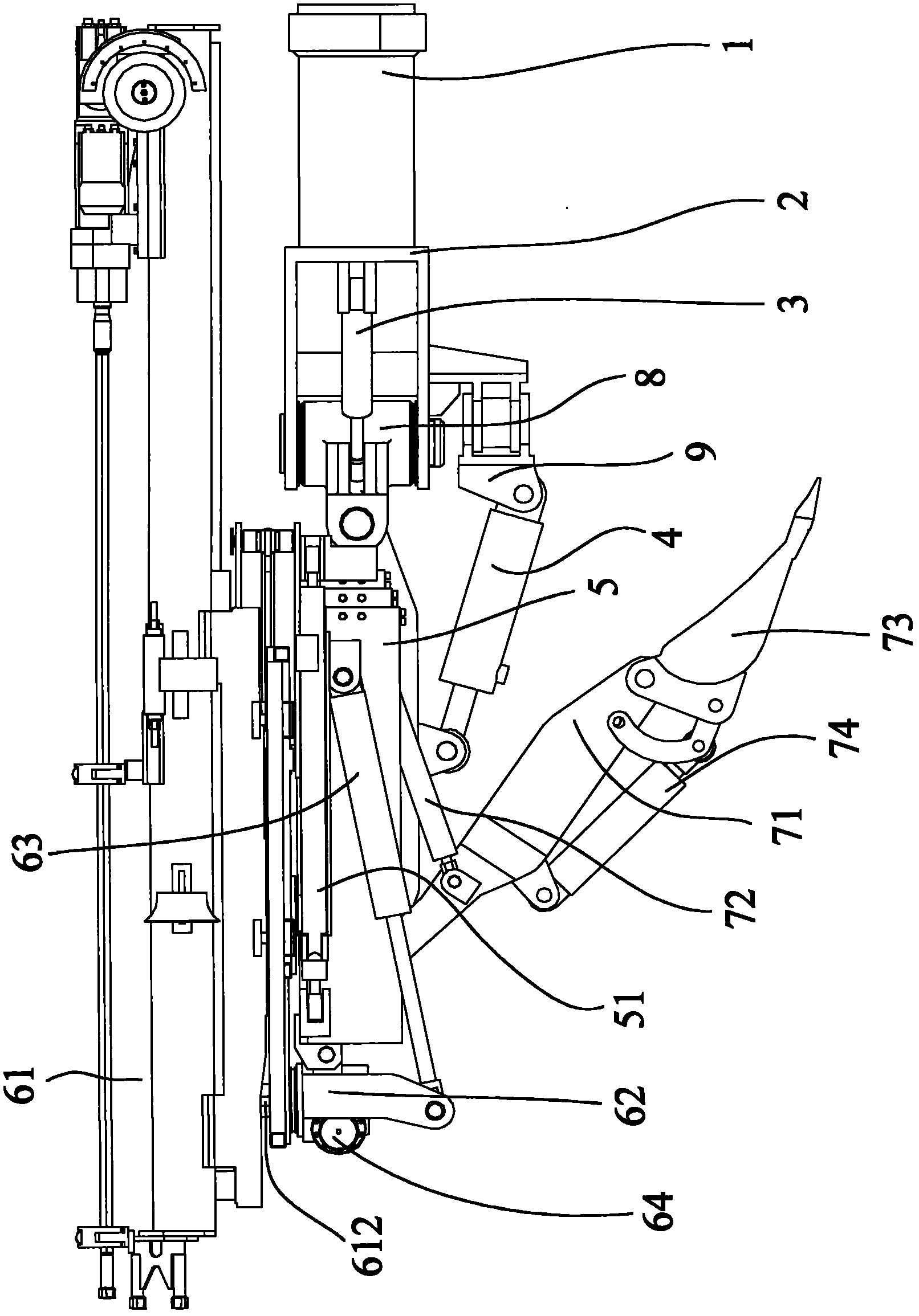
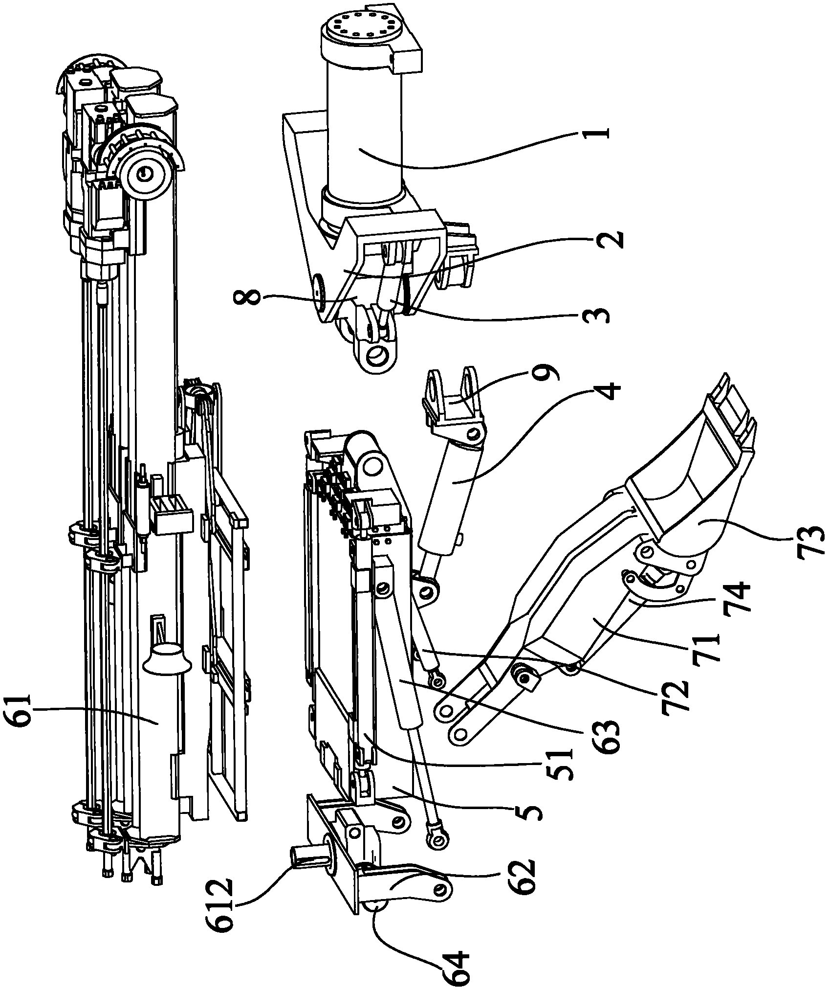
[0052] figure 1 It shows a schematic structural view of an embodiment of the working device of the drilling machine according to the present invention, figure 2 show figure 1 A perspective view of disassembly of the embodiment shown.

[0053] Such as figure 1 with figure 2 As shown, the working device of the drilling machine provided by the present invention includes a drilling assembly, an excavating assembly and a main arm assembly, and the main arm assembly is rotatably installed on the body of the working device of the drilling machine (not shown in the figure Out), the main arm assembly includes a main arm body 5, the drilling assembly and the excavation assembly can be movably installed on the main arm body 5, the drilling assembly and the The excavating assembly can be driven by the main arm body 5 to perform the same movement as the main arm body 5 .

[0054] Adopting such a technical solution, the drilling assembly and the excavating assembly are integrated int...

Embodiment 2

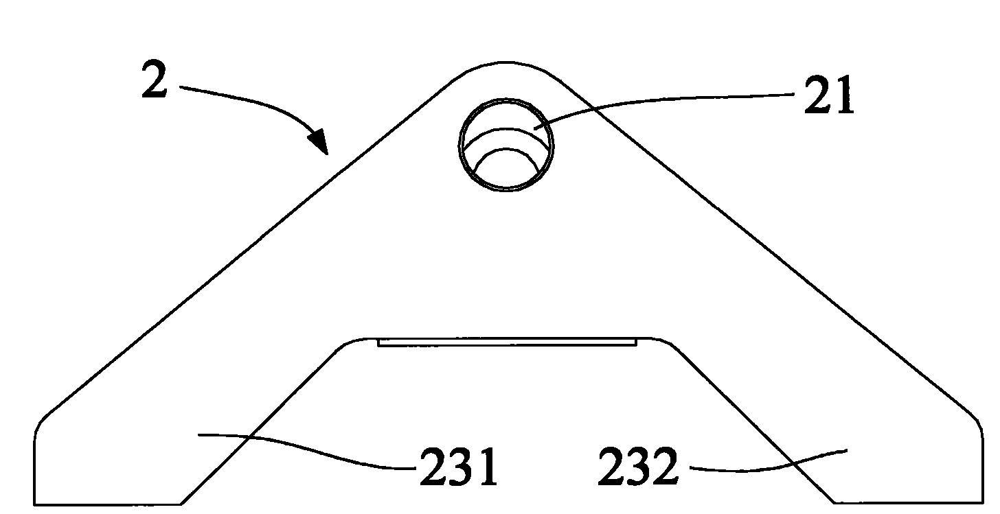
[0083] Figure 14 It shows a schematic structural view of another embodiment of the working device of the drilling machine according to the present invention, Figure 15A show Figure 14 The schematic diagram of the front view of the connecting seat of the main arm in the shown embodiment, Figure 15B show Figure 15A The schematic side view of the connecting seat of the main arm shown, Figure 15C show Figure 15A The schematic top view of the connecting seat of the main arm shown.

[0084] Such as Figure 14 As shown, Embodiment 2 mainly changes the structure of the main arm connecting seat 2 in Embodiment 1 and the connection relationship between the rotary cylinder 1 and the main arm connecting seat 2, and correspondingly changes the lifting cylinder 4 and the main arm. The connection relationship of connection socket 2 has been changed. Such as Figure 15A with 15B And as shown in 15C, the main arm connecting seat 2 is a hollow structure, the rotor of the rotary ...


PUM


Abstract

The invention provides a drill loader working device, which comprises a drilling assembly, a digging assembly and a main arm assembly, wherein the main arm assembly is arranged on a body of the drill loader working device in a rotating way and comprises a main arm body; both the drilling assembly and the digging assembly are movably arranged on the main arm body; and both the drilling assembly and the digging assembly can do the same motion as that of the main arm body when driven by the main arm body. Through the device, the problem of mutual passing of two or several large-sized equipment used in a roadway exploitation process is solved; meanwhile, the problem of complex operation brought by mutual avoidance during work of two working devices, namely the drilling assembly and the digging assembly, on the conventional drill loader is also solved; and the working efficiency is increased.

Description

technical field [0001] The invention relates to a working device of a drilling rig, and more specifically relates to a working device of a drilling rig which integrates a drilling assembly and an excavating assembly, can realize drilling operations without blind spots, and can clean gangue without leaving dead ends. Background technique [0002] At present, in the excavation process of roadways such as coal mines, mines and engineering tunnels, the excavation of rock roadways occupies a large proportion, and the excavation method is still dominated by the drill and blast method. Especially in coal mines, due to the working conditions of special substances such as gas and dust, this puts forward very strict requirements on the use conditions of drilling equipment. [0003] In the prior art, the combined use of a slag removal machine and a rock drilling jumbo is mainly used, and an integrated drilling and anchoring machine is also used. When the slag scraper and the rock dril...

Claims


Application Information

Patent Timeline
Patent Type & Authority Patents(China)
IPC IPC(8): E21D9/10E21D9/12E21B15/00E21C27/22E21C27/30
Inventor 董世安张亮吴林林
Owner JIKAI HEBEI MECHATRONICS TECH CO LTD
Learn More