
Hall thrustor capable of realizing self cleaning of polluted membrane of discharge channel and self cleaning method of Hall thrustor

A Hall thruster and discharge channel technology, applied in chemical instruments and methods, cleaning methods and appliances, thrust reversers, etc., can solve problems such as assembly errors, influence of experimental results, easy change of vacuum conditions of test devices, etc., to avoid The effect of assembly error

Inactive Publication Date: 2012-06-13
HARBIN INST OF TECH
View PDF1 Cites 11 Cited by
  • Summary
  • Abstract
  • Description
  • Claims
  • Application Information

AI Technical Summary

Problems solved by technology

[0004] The present invention solves the problem that the vacuum condition of the test device is easily changed in the existing method of opening the vacuum tank to clean the polluted film of the discharge channel of the Hall thruster, and the assembly error is easily caused during the disassembly process, which has a great impact on the experimental results. The proposed Hall thruster and its self-cleaning method can self-clean the polluted film of the discharge channel

Method used


Image

  • Hall thrustor capable of realizing self cleaning of polluted membrane of discharge channel and self cleaning method of Hall thrustor
  • Hall thrustor capable of realizing self cleaning of polluted membrane of discharge channel and self cleaning method of Hall thrustor
  • Hall thrustor capable of realizing self cleaning of polluted membrane of discharge channel and self cleaning method of Hall thrustor

Examples


specific Embodiment approach 1

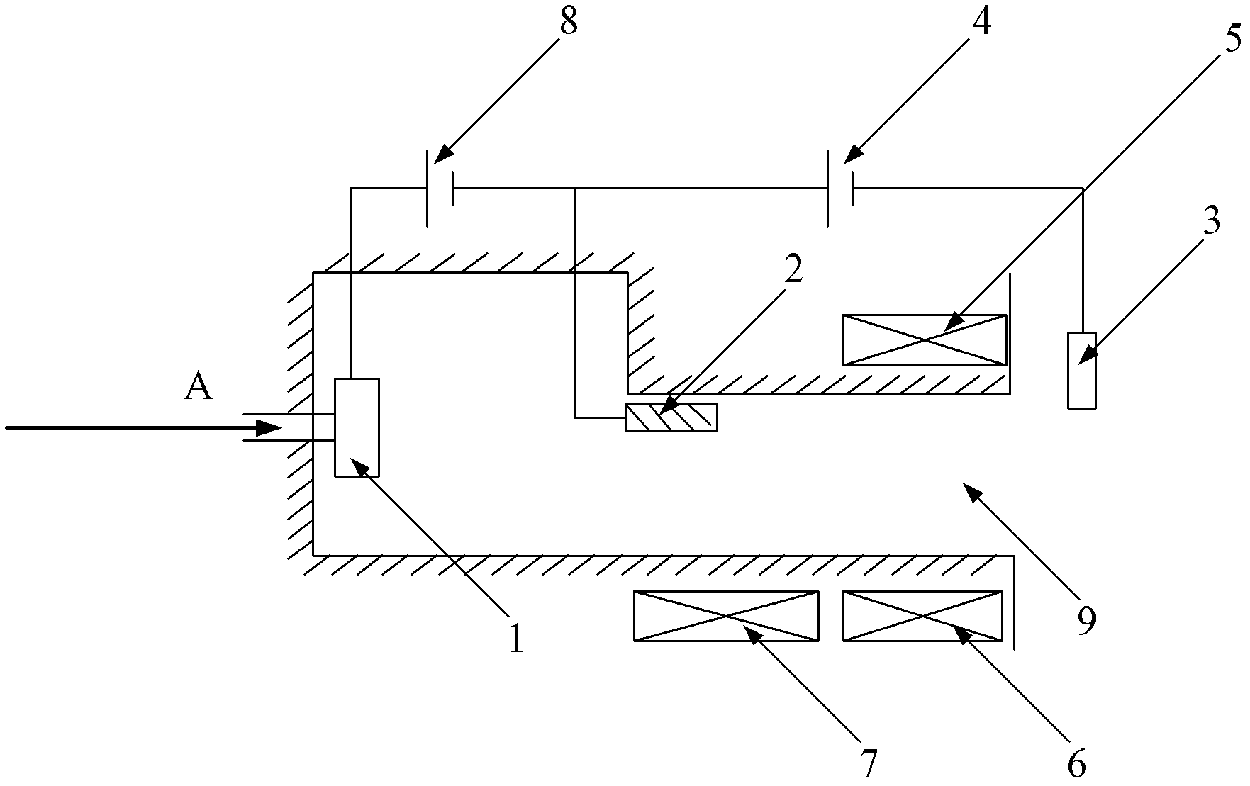
[0011] Specific implementation mode one: combine figure 1 Describe this embodiment mode, the Hall thruster that can self-clean discharge channel contamination film described in this embodiment mode, it comprises gas distributor 1, anode 2, cathode 3, discharge power supply 4, outer coil 5, inner coil 6, additional Coil 7 and discharge channel 9; the gas distributor 1 and anode 2 are arranged inside the discharge channel 9, the gas distributor 1 is arranged at the propellant A injection port in the discharge channel 9, the gas distributor 1 The gas inlet is communicated with the propellant A injection port; the anode 2 is arranged in the middle of the discharge channel 9; the cathode 3 is arranged at the outlet of the discharge channel; the anode 2 is connected to the positive pole of the discharge power supply 4, and the cathode is connected to the discharge power supply The negative pole of 4; the outer coil 5 and the inner coil 6 are symmetrically arranged on both sides of t...

specific Embodiment approach 2

[0012] Embodiment 2: The difference between this embodiment and Embodiment 1 is that the self-cleaning power supply 8 adopts a constant voltage power supply of 30-50V. Other compositions and connection methods are the same as those in Embodiment 1.

specific Embodiment approach 3

[0013] Specific embodiment three: the self-cleaning method of the Hall thruster that can self-clean the discharge channel polluted film of this embodiment as described in specific embodiment two, it is completed by the following steps:

[0014] Step 1: Pre-ionization generates self-cleaning ions; under the action of self-cleaning power supply 8, the electrons in the discharge channel 9 will move from the anode 2 to the gas distributor 1, and obtain kinetic energy from the self-cleaning pre-ionization electric field; The electrons moving from the anode 2 to the gas distributor 1 will collide with the atoms of the propellant A injected from the gas distributor 1 to generate ionization and generate self-cleaning ions;

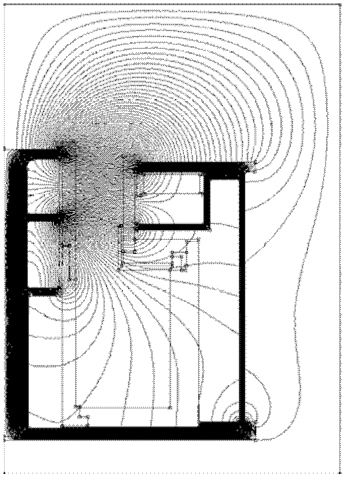
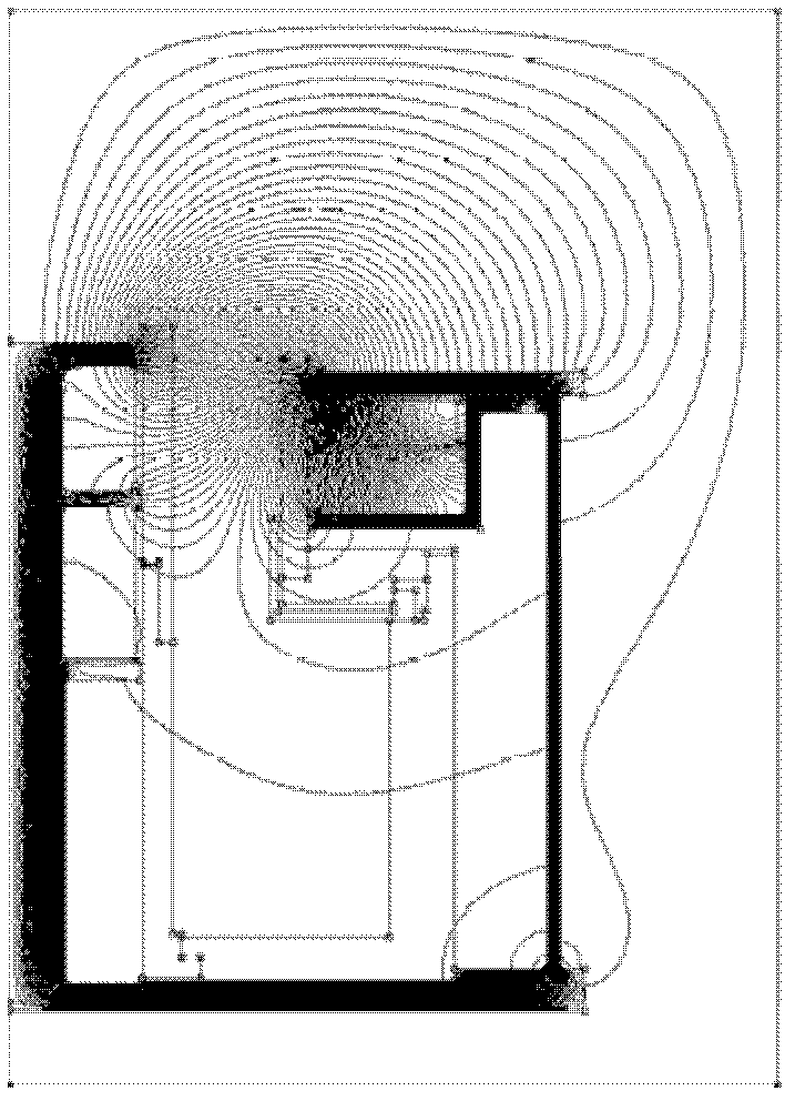
[0015] Step 2: The self-cleaning ions bombard the inner or outer wall of the discharge channel 9 under the action of the focusing magnetic field or divergent magnetic field formed by the outer coil 5, the inner coil 6 and the additional coil 7, and remove the inner...


PUM


Abstract

The invention relates to a Hall thrustor capable of realizing self cleaning of a polluted membrane of a discharge channel and a self cleaning method of the Hall thrustor, which aim to resolve problems that an exiting method for cleaning a polluted membrane of a discharge channel of a Hall thrustor by means of opening a vacuum tank is easy to change vacuum conditions of a test device, assembly errors are easy to be caused during assembly and disassembly, and experimental results are affected greatly. An anode is arranged in the middle of the discharge channel; a cathode is arranged at an outlet of the discharge channel; an outer coil and an inner coil are symmetrically arranged on two sides of the outlet of the discharge channel; the outer coil, the inner coil and an additional coil form an excitation loop after being electrified and excited; and a self cleaning power source is added between a gas distributor and the anode to form a self cleaning preionization electric field. The cleaning method includes steps of firstly, generating self cleaning ions; and secondly, forcing out an inner wall surface or an outer wall surface by the aid of the self cleaning ions to realize self cleaning of the polluted membrane of the discharge channel. An ion jet flow direction is controlled by means of changing magnetic field configuration, so that the self cleaning method is realized, and the structure of the thrustor does not need to be changed.

Description

technical field [0001] The invention relates to a Hall thruster. Background technique [0002] The Hall thruster belongs to the category of aerospace electric propulsion and is a typical representative of electromagnetic electric propulsion. It has the characteristics of simple structure, high specific impulse and high efficiency. Its structure is mainly composed of excitation circuit, cathode, anode, gas distributor and discharge channel. Its working principle is that under the approximately radial magnetic field distribution in its discharge channel, the discharge plasma between the anode and the cathode will generate a self-consistent axial electric field in the channel. Under the action of the electromagnetic field, the electrons make a circumferential Hall drift movement and move toward the anode; during the movement toward the anode, they collide with the propellant atoms injected from the gas distributor and ionize them to form ions, and the ions are in the channel ...

Claims


Application Information

Patent Timeline
Patent Type & Authority Applications(China)
IPC IPC(8): F03H1/00B08B9/02B08B13/00
Inventor 丁永杰于达仁宁中喜孙百峰
Owner HARBIN INST OF TECH
Learn More