Oscilloscope with function of dynamically recording waveform image

An oscilloscope, dynamic technology, applied in the direction of digital variable display, generating permanent records, etc., can solve the problems of data transmission and storage bottlenecks, missing information, and high cost

Inactive Publication Date: 2012-06-13
张兴杰
View PDF4 Cites 10 Cited by
  • Summary
  • Abstract
  • Description
  • Claims
  • Application Information

AI Technical Summary

Problems solved by technology

From the point of view of the implementation method, the oscilloscope directly records the sampled waveform data in units of frames. The shortcomings are: first, the bottleneck problem of data transmission and storage
If the storage depth of the oscilloscope is 2M, it means that the data volume of each waveform displayed on the screen is 2M. If the oscilloscope updates 50 waveforms per second (this is a relatively low update speed), it means that there are 100M data per second. Data needs to be transmitted and stored; at present, it is difficult to realize such data transmission and non-volatile storage, and the cost is very high; second, if the above defects are to be avoided, the method of changing the time interval of storing waveforms, that is, sacrificing The number of stored waveforms per second is used to alleviate the problem of transmission and storage. The number of stored waveforms per second is far less than the number of waveforms during actual measurement, and the playback state will be far from the actual recording state. A lot of information is lost; third, if you want to avoid the defects of the first and second above, use the method of reducing the data volume of each waveform, one is to reduce the storage depth of the oscilloscope to reduce the data volume, and the other is to re-sample the data To reduce the amount of data, but no matter which way, the final result is: in order to record the waveform, a lot of display information must be sacrificed; Fourth, if the data of two or more channels is to be recorded at the same time, the defect is more obvious

Method used


Image

  • Oscilloscope with function of dynamically recording waveform image
  • Oscilloscope with function of dynamically recording waveform image

Examples


Embodiment Construction

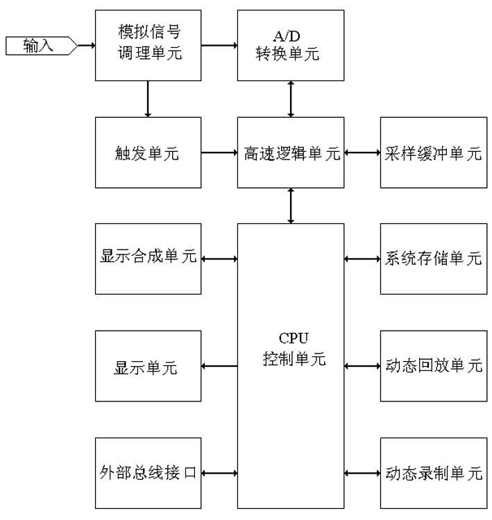
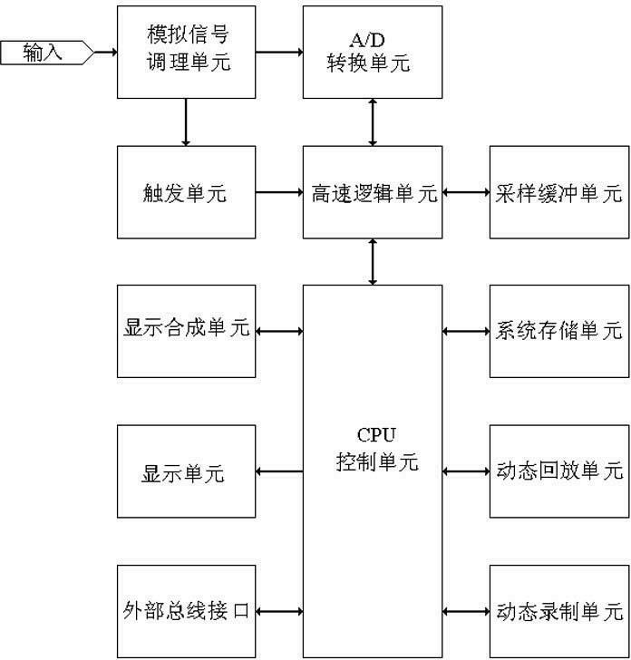
[0015] Such as figure 1 As shown, the oscilloscope with dynamically recorded waveform images described in the present invention includes an analog signal conditioning unit, an A / D conversion unit, a trigger unit, a high-speed logic unit, a sampling buffer unit, a CPU control unit, a system storage unit, a display unit, External bus interface unit, display synthesis unit, dynamic recording unit and dynamic playback unit.

[0016] The signal to be tested is sent to the trigger unit and the A / D conversion unit after being conditioned by the signal conditioning module. The high-speed logic unit controls the A / D conversion unit to sample under the trigger control of the trigger unit. The sampled data is transmitted to the Sample buffer unit. After completing a waveform acquisition, the high-speed logic unit transfers the waveform data from the sampling buffer unit to the CPU control unit, and the CPU control unit converts the image data corresponding to the screen pixels, or: the ...


PUM


Abstract

The invention discloses an oscilloscope with a function of dynamically recording a waveform image. The oscilloscope comprises an analog signal conditioning unit, an analog/digital (A/D) conversion unit, a triggering unit, a high-speed logic unit, a sampling buffering unit, a central processing unit (CPU) control unit, a system storage unit, a display unit, an external bus interface unit, a display synthesis unit, a dynamic recording unit and a dynamic playback unit, wherein a tested signal is sent into the triggering unit and the A/D conversion unit respectively after being conditioned by the signal conditioning unit; the high-speed logic unit controls the A/D conversion unit to sample under the triggering control of the triggering unit; the sampled data is transmitted to the sampling buffering unit through the high-speed logic unit; the high-speed logic unit transfers waveform data from the sampling buffering unit to the CPU control unit; and the waveform data is converted into image data corresponding to the pixel of a screen by the CPU control unit. The oscilloscope has the advantage that: an aim of recording a waveform is fulfilled by adopting an image recording method; and when recording the waveform, the oscilloscope is not restricted by the oscilloscope storage depth and the number of channels.

Description

technical field [0001] The present invention relates to oscilloscopes, and more particularly to oscilloscopes with dynamically recorded waveform images. Background technique [0002] The current digital oscilloscopes all give such an index as "storage depth", which indicates the maximum number of bytes to store a waveform, generally ranging from hundreds of bytes to hundreds of megabytes. The storage depth of hundreds of megabytes is very important for observation It is large enough for an instantaneous waveform. The storage that the oscilloscope gives the storage depth index is called static storage here, because this kind of storage cannot be carried out automatically and continuously, and a series of key operations are required manually to store a waveform, and the stored waveforms can only be stored one by one. Viewing is as static as viewing a slideshow. But if it is necessary to continuously record a rapidly changing signal, it is unrealistic to rely on the functiona...

Claims


Application Information

Patent Timeline
Patent Type & Authority Applications(China)
IPC IPC(8): G01R13/02G01R13/04
Inventor 张兴杰
Owner 张兴杰
Why Eureka
Try Eureka