High-precision current detection circuit based on CPU (Central Processing Unit)

A current detection circuit and high-precision technology, applied in the power supply field, can solve the problem of low signal sampling accuracy, and achieve the effects of improving competitiveness, reducing dependence, and improving current detection accuracy

Inactive Publication Date: 2012-06-13
WISDRI WUHAN AUTOMATION
View PDF3 Cites 8 Cited by
  • Summary
  • Abstract
  • Description
  • Claims
  • Application Information

AI Technical Summary

Problems solved by technology

[0005] The technical problem to be solved by the present invention is to provide a high-precision circuit detection circuit in order to solve the defect of low signal sampling precision in the existing circuit

Method used


Image

  • High-precision current detection circuit based on CPU (Central Processing Unit)
  • High-precision current detection circuit based on CPU (Central Processing Unit)
  • High-precision current detection circuit based on CPU (Central Processing Unit)

Examples


Embodiment Construction

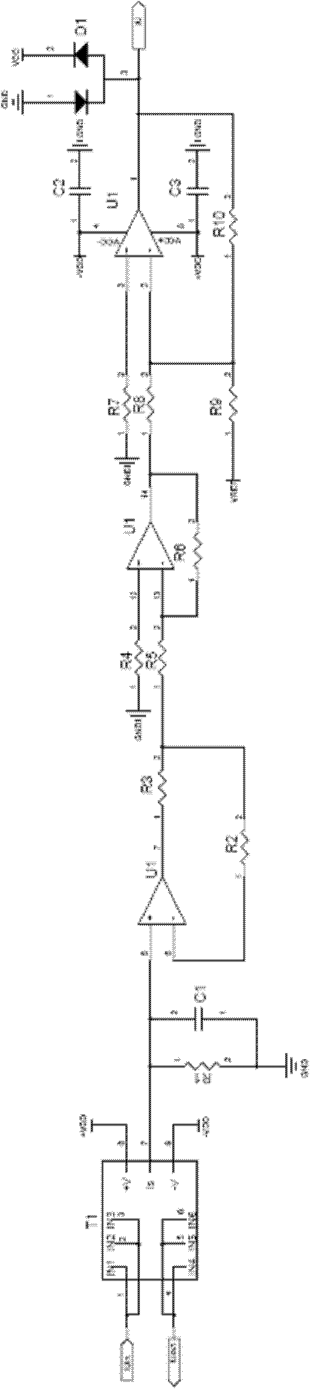
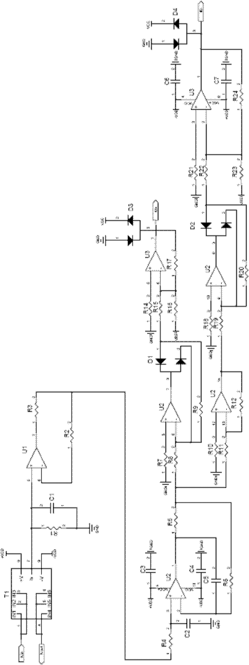
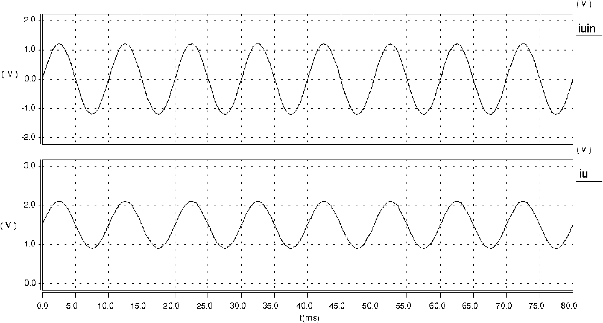
[0020] Based on the CPU high-precision current detection circuit provided by the present invention, see figure 2 , including current Hall sensing circuit, used to convert large current into low voltage signal; current conditioning circuit, used to condition the low voltage signal converted by the sensor into positive and negative half wave signals and send them to the AD port of CPU for detection; for AD The sampling value is obtained by the AD conversion formula and the current sampling combination relationship to obtain the output current value. The measured current IUin becomes a weak current IS after passing through the current Hall sensor T1. Get the voltage value IU corresponding to the circuit under test. The filter capacitor C1 is connected to both ends of the sampling resistor R1. The current IU passing through the current sensor passes through the filter circuit composed of R4 and C2 and is followed by the operational amplifier U2 and then divided into two paths. ...


PUM


Abstract

The invention relates to a high-precision current detection circuit based on a CPU (Central Processing Unit). The detection current is mainly composed of a plurality of filter capacitors, a bypass capacitor, a following resistor, an input resistor, a feedback resistor, an absolute value diode, a protected diode and an operational amplifier, wherein when the circuit works, detected current IUin passes through a current Hall sensor T1 to be converted into weak current IS; a voltage value, which corresponds to the IS, is obtained through a sampling resistor R1 and then the voltage value is carried out by operational amplification and following to obtain a voltage value IU corresponding to a circuit to be detected; the current IU, which passes through a current sensor, passes through a filtering circuit formed by a resistor R4 and the filter capacitor C2, and then is divided into two paths after the following of operational amplification U2; one path of the current passes through an absolute value circuit and a reverse uplifting circuit to obtain a positive half-wave of the current; and the other path of the current is reversed and passes through the absolute value circuit and the reverse uplifting circuit to obtain a negative half-wave of the current. The high-precision current detection circuit based on the CPU has the advantages that: a detected signal is amplified under the condition that an AD (Analog to Digital) linear zone is not changed, so that the precision can be greatly improved.

Description

technical field [0001] The invention relates to the technical field of power supplies, in particular to an output three-phase current detection circuit of a frequency converter power unit. Background technique [0002] In modern industrial applications, with the continuous development of power electronics technology, microelectronics technology and modern control theory, inverters, UPS, power supplies and other products will be used in many industrial and civil occasions. A good product needs three-phase AC The output or input current is detected in real time to meet the needs of monitoring and control. [0003] The existing methods generally use the AC signal collected by the Hall to directly raise a certain amplitude VREF through the whole to make the entire AC signal a positive value so that the AD port of the CPU is in the linear area, such as figure 1 shown. The circuit realizes three-phase output current detection, among which IUin is one phase of the three-phase out...

Claims


Application Information

Patent Timeline
Patent Type & Authority Applications(China)
IPC IPC(8): G01R19/25
Inventor 康现伟王胜勇卢家斌唐文秀李传涛李四川李海东
Owner WISDRI WUHAN AUTOMATION
Why Eureka
Try Eureka