Self-excited Buck circuit

A self-excited, circuit technology, used in electrical components, adjusting electrical variables, instruments, etc., can solve problems such as insufficient output voltage stability, achieve good adjustment rate, reduce the number of coupled inductor turns, and achieve the effect of protection

Active Publication Date: 2014-11-19
BEIJING INST OF CONTROL ENG
View PDF5 Cites 0 Cited by
  • Summary
  • Abstract
  • Description
  • Claims
  • Application Information

AI Technical Summary

Problems solved by technology

The invention solves the problem of insufficient output voltage stability in the existing self-excited Buck circuit

Method used


Image

  • Self-excited Buck circuit
  • Self-excited Buck circuit
  • Self-excited Buck circuit

Examples


Embodiment Construction

[0022] The specific embodiments of the present invention will be further introduced below in conjunction with the accompanying drawings.

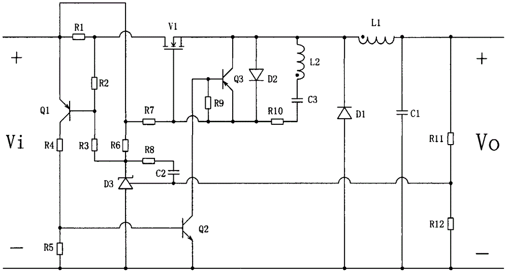
[0023] Such as figure 2 As shown, the present invention is the self-excited Buck conversion circuit, including: inductor L1, capacitor C1, diode D1, switch tube V1 and output sampling resistors R11, R12, and also includes current sampling resistor R1, PNP transistor Q1, PI Regulating circuit, self-excited drive circuit. The PI regulation circuit includes a reference regulator D3, a capacitor C2 and resistors R6 and R8. The self-excited drive circuit includes a coupling inductor L2, a capacitor C3, and a resistor R10.

[0024] In the circuit, Vi and Vo are the input and output voltages of the converter respectively. Inductor L1, capacitor C1, diode D1, and switch tube V1 constitute the Buck main circuit. In the Buck main circuit, the current sampling resistor R1 is connected in series with the Buck main circuit. Among them, one end of ...


PUM


Abstract

The invention discloses a self-excited Buck circuit, which comprises an inductor L1, a capacitor C1, a diode D1, a switching tube V1 and output sampling resistors R11 and R12, wherein the inductor L1, the capacitor C1, the diode D1 and the switching tube V1 form a Buck main circuit; and the output sampling resistors R11 and R12 are connected in series with each other, and then are connected in parallel with a load end. The self-excited Buck circuit further comprises a current sampling resistor R1, a PNP type triode Q1, a proportion-integration (PI) regulation circuit and a self-excited driving circuit. By the self-excited Buck circuit, the problem of low output voltage stability of the conventional self-excited Buck circuit is solved.

Description

technical field [0001] The invention relates to a self-excited Buck circuit. Background technique [0002] In small and medium power applications, compared with other excited DC / DC converters and linear voltage regulator circuits, self-excited DC / DC converters have the advantages of simple circuit, fewer components, high efficiency and low cost. [0003] At present, the main switching tube of the self-excited Buck converter is generally implemented by a bipolar transistor; the switching tube is controlled by adding an auxiliary winding to the output filter inductor; by comparing the signal after sampling the output voltage with the voltage Vbe of the triode, The turn-off control of the switching tube is realized through a certain circuit, and then the purpose of stabilizing the output voltage is achieved. [0004] Chinese Patent No. ZL99108088.2 discloses a self-excited Buck converter circuit, such as figure 1 shown. Vi and Vo are the DC input and output voltages of the c...

Claims


Application Information

Patent Timeline
Patent Type & Authority Patents(China)
IPC IPC(8): H02M3/156
Inventor 孙定浩杜建华王立伟彭政叶东东李山
Owner BEIJING INST OF CONTROL ENG
Why Eureka
Try Eureka