

Automatic tee shaping equipment and shaping method thereof
A tee and equipment technology, which is applied in the field of automatic tee shaping equipment and its shaping, can solve the problems that the main pipe mouth and branch pipe mouth cannot guarantee the verticality and concentricity, the yield rate is unstable, and the yield rate is reduced, so as to ensure the quality and appearance, simplification of processing procedures, good verticality and concentricity
- Summary
- Abstract
- Description
- Claims
- Application Information
AI Technical Summary
Problems solved by technology
Method used
Image

Examples
Embodiment 1
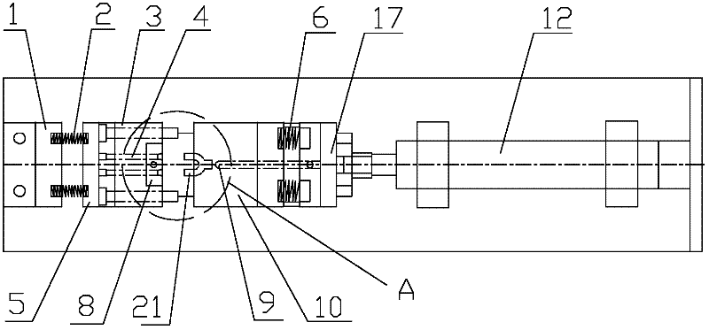
[0031] An automatic three-way shaping device of the present invention is aimed at the three-way 21, and is used for reducing the diameter of the branch pipe end of the three-way 21 to x and expanding the diameter of the main port to y.
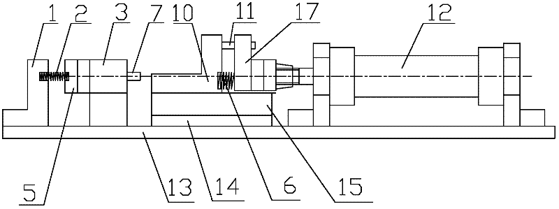
[0032] Such as Figure 1-4 shown. The automatic three-way shaping equipment includes a fixed plate 1 of the auxiliary shaping part coaxially arranged on the bottom plate 13, an auxiliary shaping part, a main shaping part and a hydraulic cylinder 12, wherein the main shaping part is arranged between the auxiliary shaping part and the hydraulic cylinder 12. The base plate is provided with a planar slide rail 14 for the movable part of the main shaping part to slide back and forth above.
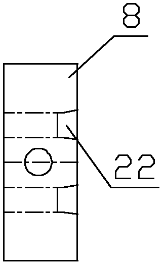
[0033] The shrinking die fixing plate 3 of the auxiliary shaping part is fixed on the bottom plate 13, and the shrinking die 8 is set. There are two ejector pin through holes for the ejector pin 4 to slide back and forth in the shrinking die fixed plate 3, an...
Embodiment 2
[0041] On the basis of the first embodiment, the movement structure of the stripping needle in the secondary shaping part is changed. The secondary shaping part is composed of a push rod fixing plate and a driving cylinder thereof, replacing the fixing plate 1, auxiliary spring and push rod in the first embodiment. Wherein the driving cylinder is arranged on one side of the shrinking die, and the end surface of the fixed plate is fixed with a stripping needle, and the process and return of the stripping needle are controlled by the driving cylinder, wherein the driving cylinder is a hydraulic cylinder or an air cylinder. The rest of the structure is the same as that of Embodiment 1, and will not be repeated here.
Embodiment 3
[0043] see Figure 5 , On the basis of Embodiment 1, change the movement structure of the ejector needle in the secondary shaping part. The auxiliary shaping part includes a push rod fixing plate 5, a push plate 18, and a cross bar 19, replacing the fixing plate 1, the auxiliary spring 2 and the push rod 7 in the first embodiment. The end face of the ejector rod fixed plate is fixed with a material ejection needle and a push plate 18, and the push plate is provided with a material avoidance groove, and a cross bar 19 fixed on the supporting plate is inserted in the material escape groove. In the initial state, the ejector rod fixing plate 5 is attached to the shrinking mold fixing plate 3, and the ejector needle is inserted into the shrinking mold cavity. It can move to the left until it reaches the left end of the ejection avoidance groove, the cross bar 19 pushes the push plate 18 to move to the left, so that the ejector pin fixed plate 5 drives the ejector needle to gradua...
PUM
 Abstract
Description
Claims
Application Information