Light harvesting cutter

A cutter and light-collecting technology, applied in welding equipment, metal processing equipment, manufacturing tools, etc., can solve problems such as increased equipment purchase and use costs, high-priced laser generators, unfavorable operation and maintenance, etc., to improve resistance to heat The ability to deform, ensure the cutting effect, and ensure the effect of cutting accuracy

Inactive Publication Date: 2012-06-20
夏致俊
View PDF4 Cites 2 Cited by
  • Summary
  • Abstract
  • Description
  • Claims
  • Application Information

AI Technical Summary

Problems solved by technology

[0002] Existing devices that use light energy for metal cutting are usually laser cutters. This type of equipment requires an expensive laser generator

Method used


Image

  • Light harvesting cutter
  • Light harvesting cutter
  • Light harvesting cutter

Examples


Example Embodiment

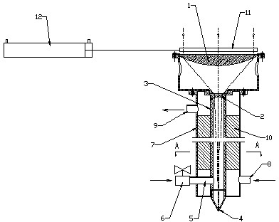
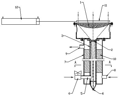
[0014] As shown in the figure, the light-collecting cutter includes a convex lens 1 and a concave lens 2 coaxially arranged from top to bottom. A section of inner tube 3 is connected below the concave lens, and a cutting nozzle 4 with an opening is arranged at the lower end of the inner tube; convex lens 1 A single-wavelength parallel incident light source is set above. The focus of parallel light below the convex lens is below the concave lens. The parallel light is condensed by the convex lens and then refocused by the concave lens.
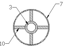
 The refocused focus is near the bottom of the cutting nozzle.

[0015] The upper end of the inner tube 3 is hermetically connected with the concave lens 2, and the inner cavity of the inner tube is connected with a compressed air source through an air inlet tube 5 and an air inlet valve 6. An outer tube 7 is sheathed around the inner tube. The outer tube is provided with a cooling liquid inlet 8 and a cooling liquid outlet 9 connected to the cooling ...


PUM


Abstract

The invention relates to a device for cutting metal by utilizing pyrogenicity of light energy, in particular to a light harvesting cutter. The light harvesting cutter comprises a convex lens and a concave lens which are arranged coaxially from top to bottom, wherein a section of inner tube is connected below the concave lens, and a cutting nozzle with an open hole is arranged at the lower end of the inner tube; a parallelly-incident light source is arranged above the convex lens; and after passing through the convex lens to converge, parallel light passes through the concave lens to be focused, and refocused focal points are positioned below the cutting nozzle. By the light harvesting cutter, the strength of incident light rays on a unit area is enhanced, and the operating range of the light harvesting cutter in the axial direction is increased greatly by light beams closed to parallel light, so that a cutting effect which is similar to lasers is achieved; and the light harvesting cutter can be used for cutting the metal, has a simple structure and is convenient to run and maintain.

Description

technical field [0001] The invention relates to a device for cutting metal by using light energy to generate heat, in particular to a light-collecting cutter. Background technique [0002] Existing devices that use light energy for metal cutting are usually laser cutters. This type of equipment requires an expensive laser generator, which greatly increases the purchase and use costs of the equipment. At the same time, its complex structure is not conducive to operation and maintenance. . Contents of the invention [0003] The technical problem to be solved by the present invention is to provide a light-collecting cutter that can be used for metal cutting, has a simple structure, and is convenient for operation and maintenance. [0004] The light-collecting cutter of the present invention includes a convex lens and a concave lens arranged coaxially from top to bottom, a section of inner tube is connected below the concave lens, and a cutting nozzle with an opening is arran...

Claims


Application Information

Patent Timeline
IPC IPC(8): B23K28/00
Inventor 夏致俊
Owner 夏致俊
Why Eureka
Try Eureka