
CCD (charge-coupled device) tool setting and monitoring apparatus for precision machining of complicated microstructural parts

A precision machining and monitoring device technology, applied in the direction of automatic control devices, feeding devices, metal processing, etc., can solve the problems of inconvenient operation, inability to realize fast tool setting, and low tool setting accuracy, so as to save time and energy Easy to move, easy to operate

Active Publication Date: 2013-08-28
HARBIN INST OF TECH
View PDF5 Cites 0 Cited by
  • Summary
  • Abstract
  • Description
  • Claims
  • Application Information

AI Technical Summary

Problems solved by technology

[0003] In order to solve the problems of inconvenient operation, low precision of tool setting, and inability to realize fast tool setting when using the existing tool setting device during precision machining of microstructure parts, the present invention further provides a CCD sensor for precision machining of microstructure parts. Knife and monitoring device

Method used


Image

  • CCD (charge-coupled device) tool setting and monitoring apparatus for precision machining of complicated microstructural parts
  • CCD (charge-coupled device) tool setting and monitoring apparatus for precision machining of complicated microstructural parts
  • CCD (charge-coupled device) tool setting and monitoring apparatus for precision machining of complicated microstructural parts

Examples


specific Embodiment approach 1

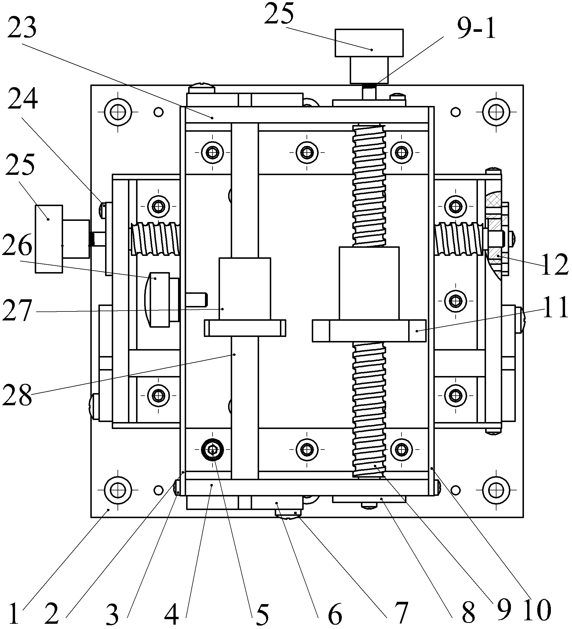
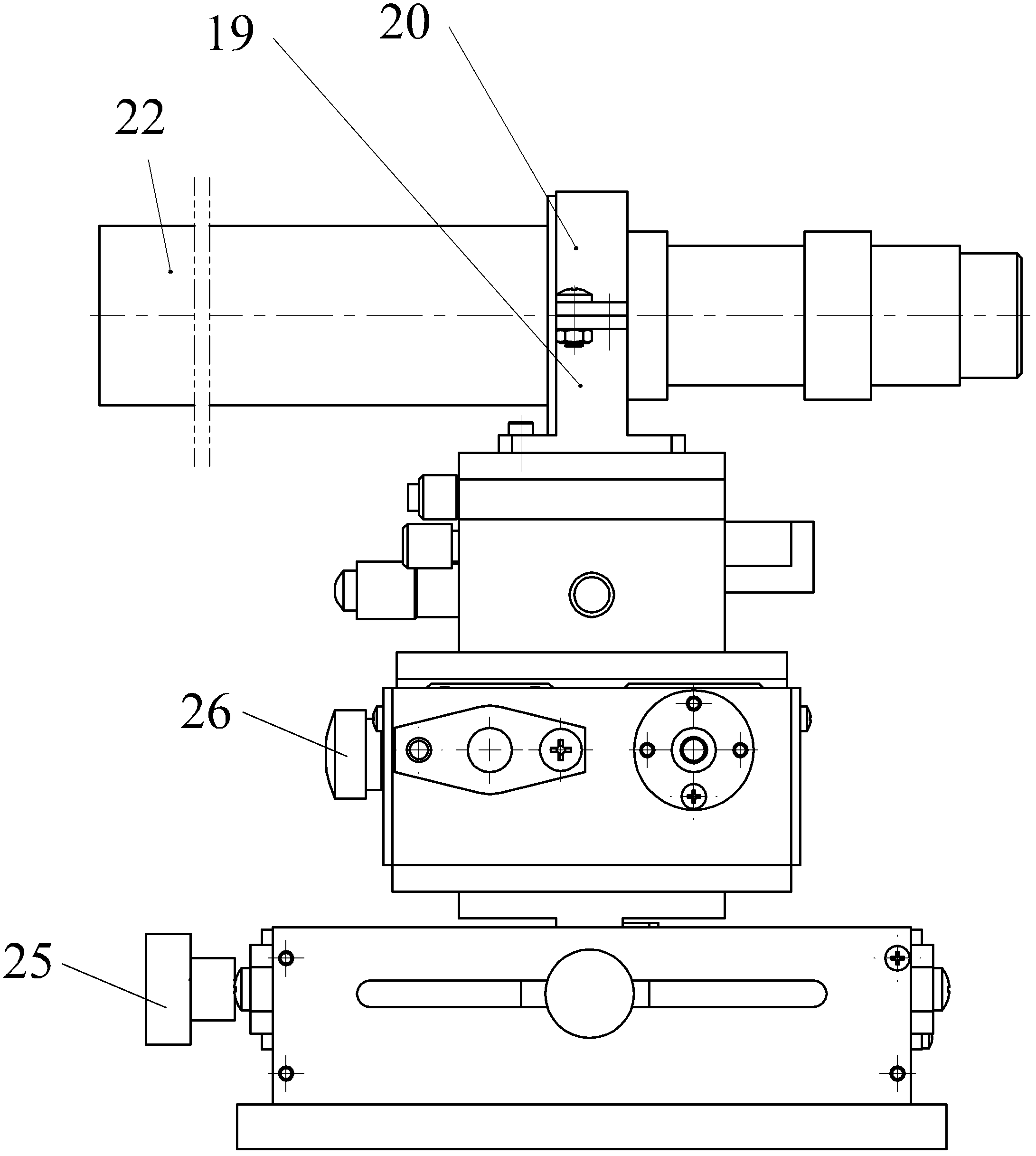
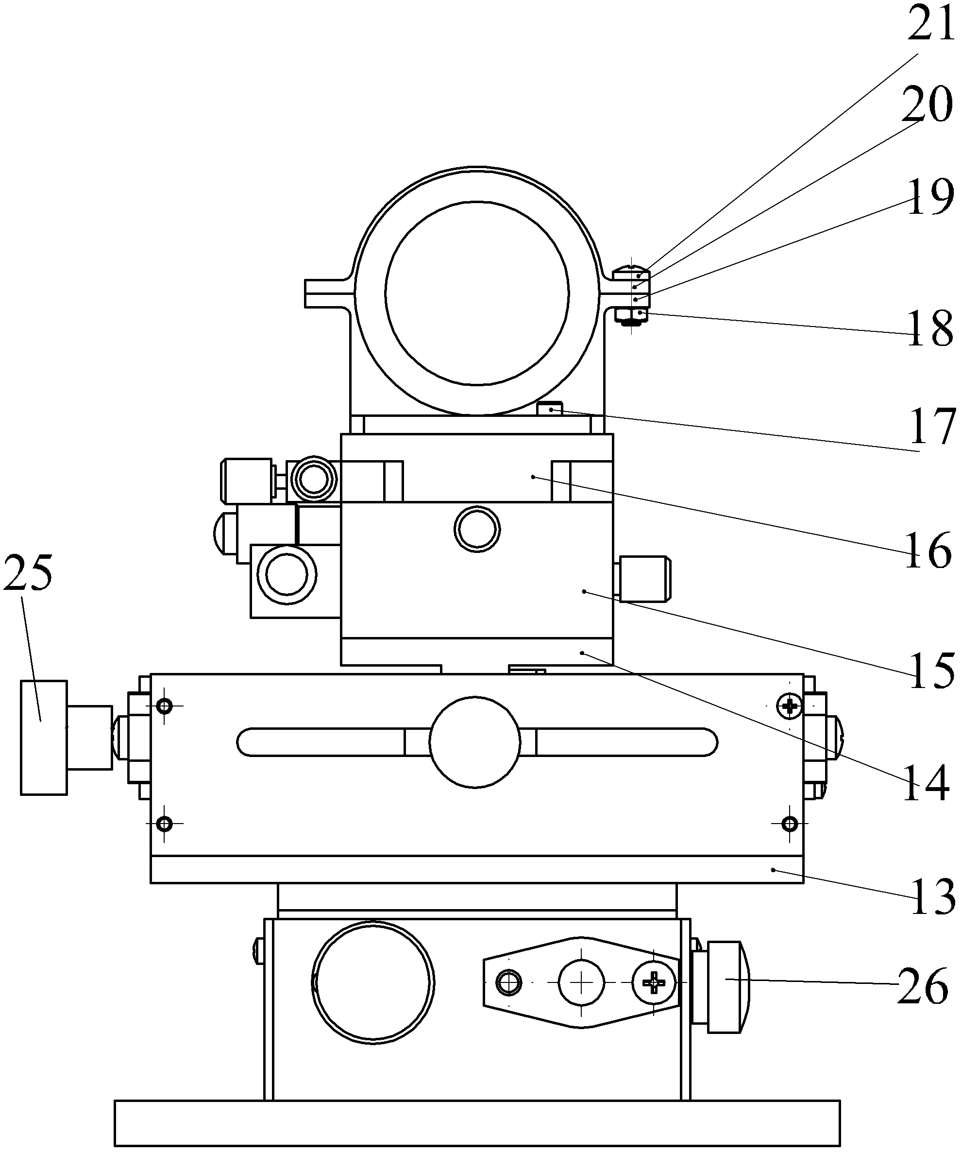
[0018] Specific implementation mode one: as Figure 1-9 As shown, the CCD tool setting and monitoring device platform base 1 of the precision machining of microstructure parts described in this embodiment and the rough adjustment part, fine adjustment part and CCD micromagnifying glass installed on the platform base 1; define the CCD microscopic magnifying glass The axis of the zoom lens 22 is the X-axis, the axis of the electric spindle 29 that controls the rotation of the precision machining tool for the microstructure is the Z-axis, and the Y-axis passes through the intersection of the X-axis and the Z-axis and is perpendicular to the plane defined by the X-axis and the Z-axis The device also includes a coarse adjustment connecting plate 13 and a connecting piece 14; the coarse adjustment part is composed of two X-axis movement adjustment ball screw mechanisms and a Z-axis movement adjustment ball screw mechanism with the same structure, and the fine adjustment It is partia...

specific Embodiment approach 3

[0024] Specific implementation mode three: as Figure 1-9 As shown, the zoom lens 22 of the CCD micromagnifier in this embodiment is installed on the precision turntable 16 through the fixed lower base 19 and the fixed upper base 20 . Other components and connections are the same as those in the first embodiment.

specific Embodiment approach 4

[0025] Specific implementation mode four: as Figure 1-9 As shown, Bakelite handles 25 are installed on the protruding ends 9 - 1 used for adjustment in the X-axis movement adjustment ball screw mechanism and the Z-axis movement adjustment ball screw mechanism in this embodiment. Other compositions and connections are the same as those in the first, second or third embodiment.

[0026] The specific process description of using the device of the present invention to monitor the tool setting:

[0027] 1. The basic conditions that need to be met when designing the tool setting monitoring device:

[0028] The device uses a high-magnification CCD microscope magnifier (model: MT6350), and its magnification can reach up to 1200 times. Due to its high magnification, its working distance is small, only about 30mm, set as d. Such as figure 1 As shown, let the distance between the end face of the CCD lens and the tip of the tool be L. To carry out the tool setting operation, the pos...


PUM


Abstract

A CCD (charge-coupled device) tool setting and monitoring apparatus for precision machining of microstructural parts relates to a tool setting and monitoring device, aims to solve problems that existing tool setting devices are inconvenient in operation, low in tool setting precision and incapable of realizing quick tool setting and the like and comprises a coarse adjustment portion and a fine adjustment portion. The coarse adjustment portion includes an X-axis moving adjustment ball-screw mechanism and a Y-axis moving adjustment ball-screw mechanism which have the same structure. The fine adjustment portion consists of a shifting platform and a precision turntable. The X-axis moving adjustment ball-screw mechanism is fixedly mounted on a base of the shifting platform through angular support parts and angular support symmetrical parts, the Z-axis moving adjustment ball-screw mechanism is disposed on the X-axis moving adjustment ball-screw mechanism, the Z-axis moving adjustment ball-screw mechanism and the X-axis moving adjustment ball-screw mechanism are in crossed arrangement and are connected through coarse adjustment connecting plates, the Z-axis moving adjustment ball-screw mechanism is connected with the shifting platform through connectors, and the shifting platform is connected with the precision turntable. The CCD tool setting and monitoring apparatus is mainly applied to precision machining of microstructural parts.

Description

technical field [0001] The invention relates to a tool setting and monitoring device for precision machining of microstructure parts. Background technique [0002] With the increasing development of modern science and technology, the demand for high-precision microstructure components is increasing for cutting-edge products in various industries, so the demand for microstructure processing devices is also increasing. In the process of microstructure machining, whether the design of the tool setting monitoring device is reasonable or not has an important influence on the machining accuracy and surface quality of the microstructure. Furthermore, a reasonable monitoring device plays a very important role in the real-time monitoring of tool wear and tear and processing. For example, in the field of fusion energy, the application of optical crystals is very common, but micro-defects such as cracks and pits with a size of about 0.05mm-0.5mm are prone to occur during the processin...

Claims


Application Information

Patent Timeline
Patent Type & Authority Patents(China)
IPC IPC(8): B23Q17/22B23Q17/24B23Q15/22
Inventor 陈明君肖勇吴春亚郑庭倪海波程健周文清
Owner HARBIN INST OF TECH
Learn More