Wheel-rail load-increasing device for railway vehicle

A rail vehicle, wheel rail technology, applied in the field of rail vehicle wheel rail loading device, can solve the problems of large rubber deformation hysteresis effect, large rolling resistance, small bearing capacity, etc. The effect of the coefficient of friction

Inactive Publication Date: 2012-06-20
TONGJI UNIV
View PDF8 Cites 5 Cited by
  • Summary
  • Abstract
  • Description
  • Claims
  • Application Information

AI Technical Summary

Problems solved by technology

However, due to the large deformation of the tire, the load-carrying capacity is smaller than that of the steel wheel with the same diameter; the deformation hysteresis effect of the rubber is also large, resulting in a correspondingly large rolling resistance, which is also a disadvantageous factor for tire-type rail vehicles.

Method used


Image

  • Wheel-rail load-increasing device for railway vehicle
  • Wheel-rail load-increasing device for railway vehicle
  • Wheel-rail load-increasing device for railway vehicle

Examples


Embodiment

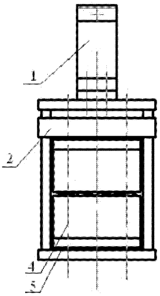
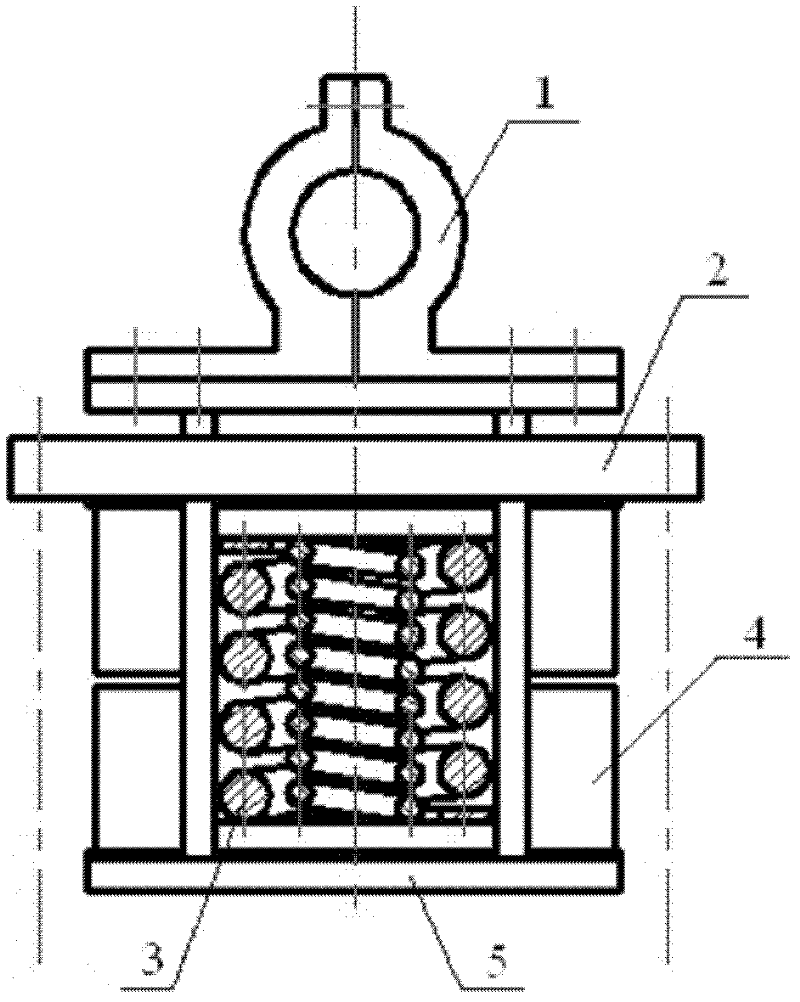
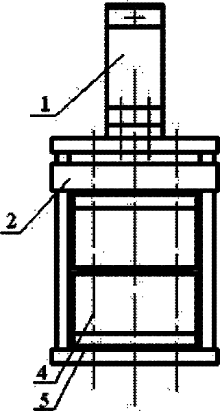
[0021] A rail vehicle wheel rail loading device, its structure is as follows Figure 1-2 As shown, the loading device includes a shaft-holding boom 1, a frame 2, a double coil spring 3, an electromagnet and its winding 4, and a magnetic gasket 5. The shaft-holding boom 1 is welded on the top of the frame 2, and the frame 2 adopts The frame structure is hollow in the middle, the double coil spring 3 is arranged in the middle of the frame 2, the electromagnet and its winding 4 are arranged on both sides of the frame 2, and the magnetic-absolute gasket 5 is arranged at the bottom of the frame.

[0022] Among them, the frame 2 and the shaft-holding boom 1 are made of ordinary steel structure beams of 270*120mm and 170*120mm, and elastic beams of 170*120mm respectively, and the elastic beams and ordinary steel structure beams are connected by welding through steel structure side columns.

[0023] Bolts are arranged at the lower part of the double-coil spring 3 , and the length of t...


PUM


Abstract

The invention relates to a wheel-rail load-increasing device for a railway vehicle, comprising an axial suspension boom (1), a framework (2), a dual-coil spring (3), an electromagnet and the winding thereof (4) and a magnetically-insulated gasket (5), wherein the axial suspension boom (1) is welded on the top of the framework (2); the framework (2) is a frame-type structure with a hollow middle; the rewinding spring (3) is disposed at the middle of the framework (2); the electromagnet and the winding thereof (4) are disposed at the both sides of the framework (2); and the magnetically-insulated gasket (5) is disposed on the bottom of the framework. Compared with the prior art, the wheel-rail load-increasing device for a railway vehicle disclosed by the invention can improve climbing capacity and change the positive pressure on steel rail by wheel set when the vehicle runs in upward slope, downward slope and flat slope, thereby freely changing the traction of the vehicle and enabling the vehicle to be of high service life and safety.

Description

technical field [0001] The invention belongs to the technical field of rail transportation equipment, in particular to a wheel-rail loading device for rail vehicles. Background technique [0002] Most of the traditional rail transit systems use the wheel-rail transit system, that is, the steel wheel rail transit system. Its advantages lie in its excellent self-guiding ability and low running resistance. However, it is the small frictional resistance between steel and steel that makes the vehicle run, especially during climbing, with insufficient adhesion and difficult climbing. The slope of the existing main line railway and urban rail transit generally does not exceed 35‰. Relatively speaking, the traditional rubber tire used in the tire transportation system has a large adhesion area and a high adhesion coefficient to the track surface, and can exert a large wheel-rail adhesion force. The adhesion area and friction coefficient increase with the increase of normal pressur...

Claims


Application Information

Patent Timeline
Patent Type & Authority Applications(China)
IPC IPC(8): B61F13/00B61K13/00
Inventor 张济民张泽立
Owner TONGJI UNIV
Why Eureka
Try Eureka